

Tilting and folding device for a treadmill
a folding device and treadmill technology, applied in the field of treadmills, can solve the problems of high cost and achieve the effect of improving the shortcomings of the conventional folding devi
- Summary
- Abstract
- Description
- Claims
- Application Information
AI Technical Summary
Benefits of technology
Problems solved by technology
Method used
Image


Examples
second embodiment
[0036]FIG. 10 shows the present invention, wherein the support device 4 replaces the two links 5 as disclosed in the previous embodiment by two retractable units 7. The two retractable units 7 are located to the two insides of the track bed 2 and each comprises an inner tube 70 and an outer tube 71 in which the inner tube 70 is retractably inserted. A biasing unit, such as a compressed air or spring (not shown) is located in the outer tube 71 so as to normally push the inner tube 70 out from the outer tube 71. The outer tube 71 has one end pivotably connected to the base 1 and the inner tube 70 extends beyond the connection portion 21 and is pivotably connected to the inside of the track bed 2.
[0037]As shown in FIG. 11, when the threaded rod 62 extends, the arm 3 pivots the front end of the track bed 2. As shown in FIG. 12, when the threaded rod 62 extends, the inner tube 70 extends and supports the track bed 2, when the threaded rod 62 continuously extends, the rear end of the trac...
third embodiment
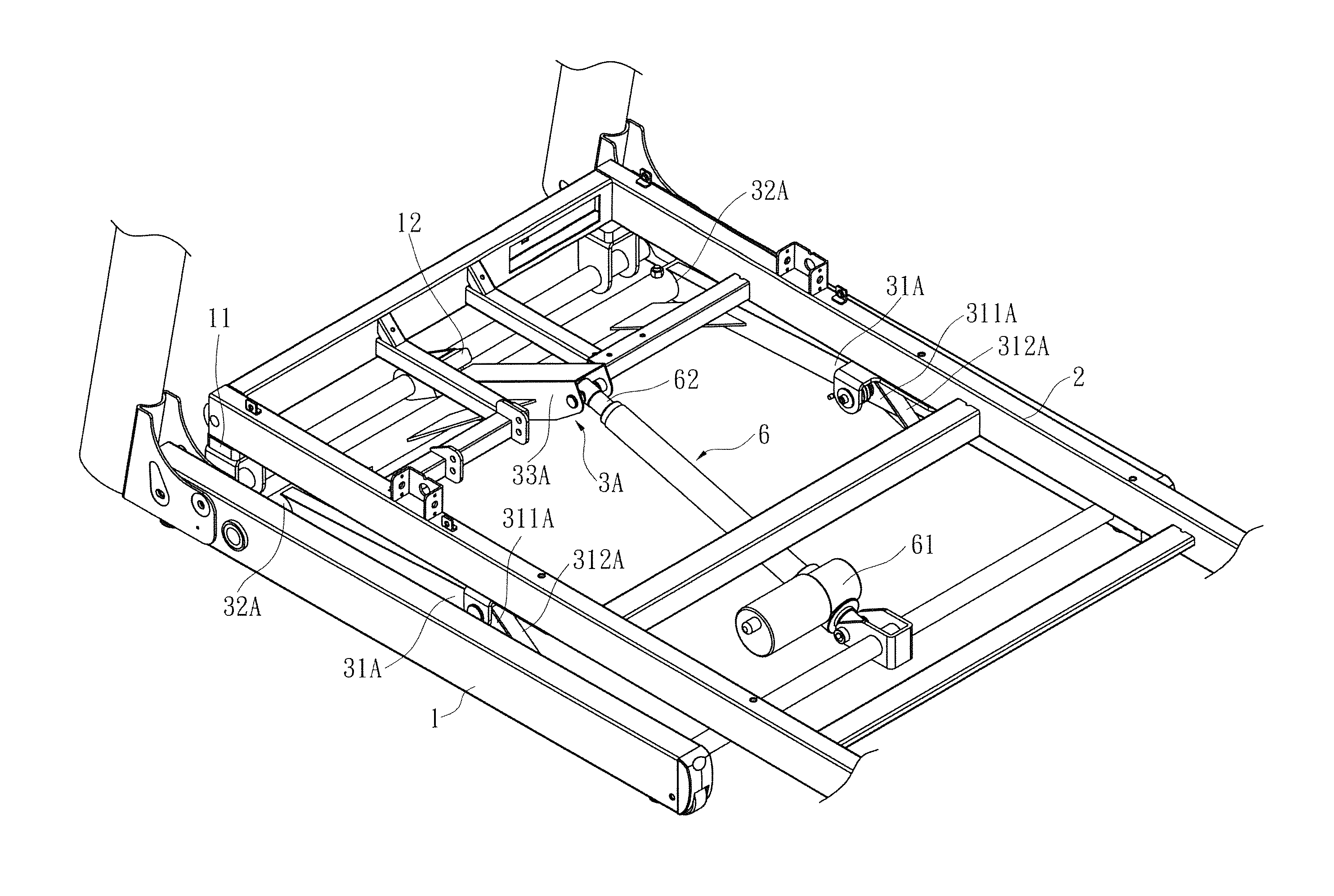
[0038]FIG. 13 shows the third embodiment, wherein the arm 3A has a first pivotal end 31A, a second pivotal end 32A and a pivotal portion 33A. The support device 4 comprises a support portion 311A fixed to the first pivotal end 31. The support portion 311A is moved with the arm 3 and has a contact face 312A. The arm 3A is pivotably connected to the two sides of the track bed 2 at the support portion 311A. The contact face 312A supports the underside of the track bed 2. The pre-set stroke starts from the track bed 2 at the horizontal position to the position where the contact face 312A supports the underside of the track bed 2.
[0039]As shown in FIG. 14, the threaded rod 62 extends to pivot the arm 3A upward and the front end of the track bed 2 is lifted. When the track bed 2 is lifted to a height, the support portion 311A supports the track bed 2. As shown In FIG. 15, when the threaded rod 62 continuously extends, because the track bed 2 is supported by the support portion 311A, the r...
PUM
 Abstract
Description
Claims
Application Information