Insufflating-exsufflating system

a technology of insufflation and exsufflation, which is applied in the direction of mechanical equipment, valves, operating means/releasing devices, etc., can solve the problem of no control over the flow of gas

Inactive Publication Date: 2015-08-25
KONINKLIJKE PHILIPS ELECTRONICS NV
View PDF11 Cites 4 Cited by
  • Summary
  • Abstract
  • Description
  • Claims
  • Application Information

AI Technical Summary

Problems solved by technology

Conventional insufflation-exsufflation systems tend to be relatively rudimentary devices that require manual operation and provide little to no control over the flow of gas to and from the patient during insufflation-exsufflation.

Method used


Image

  • Insufflating-exsufflating system
  • Insufflating-exsufflating system
  • Insufflating-exsufflating system

Examples


Embodiment Construction

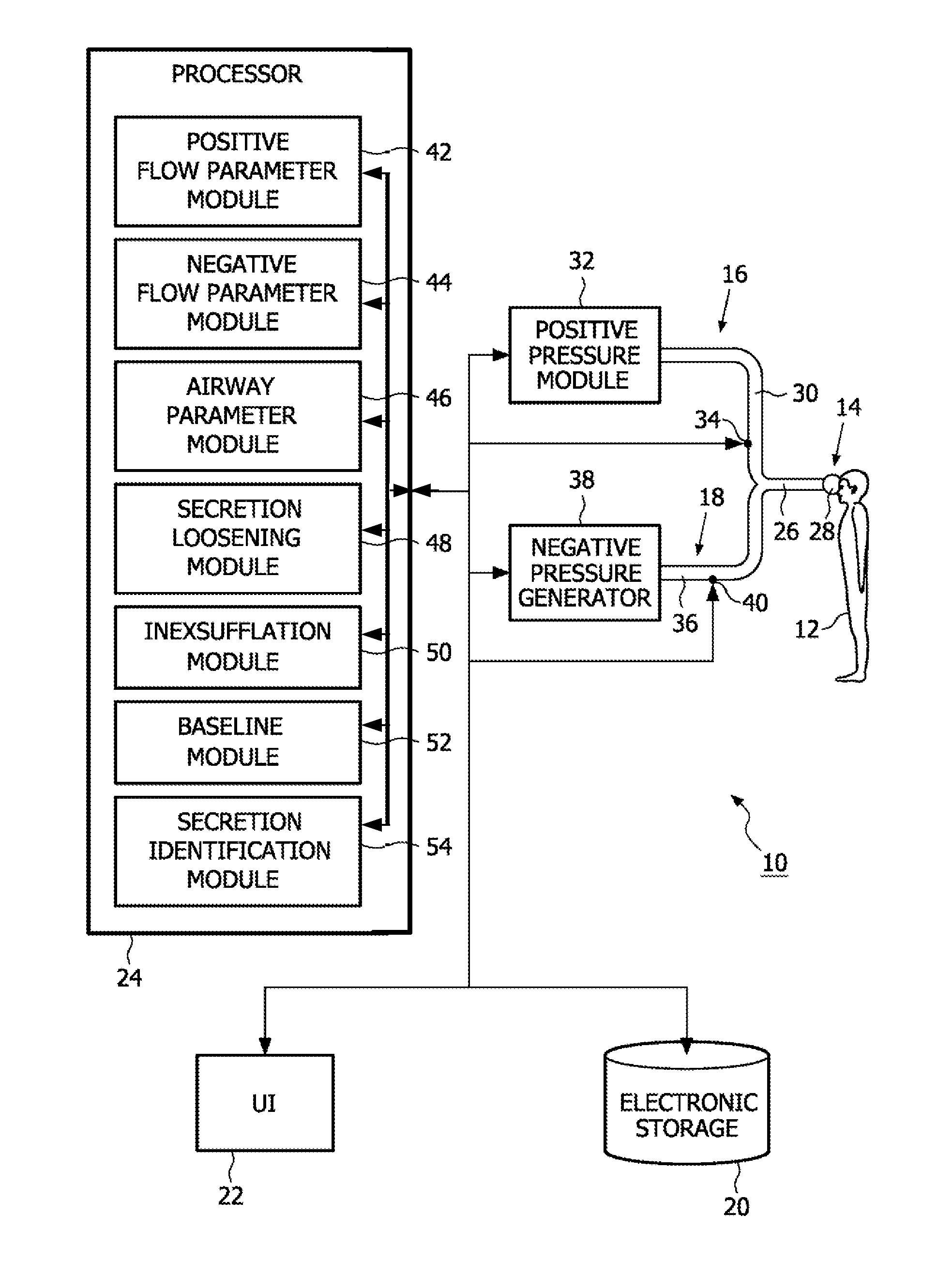
[0024]FIG. 1 illustrates a system 10 configured to insufflate-exsufflate (“inexsufflate”) a subject 12. The configuration of the components of system 10 enable subject 12 to be inexsufflated with an enhanced efficiency, with an enhanced precision, with an enhanced convenience to users (e.g., caregivers, etc.), and / or with other enhancements. In particular, system 10 may be configured to execute a predetermined routine that first loosens secretions within subject 12 prior to moving the secretions up the airway (e.g., toward the mouth) through an inexsufflation routine.

[0025]In a first embodiment, system 10 initiates the loosening routine and / or the inexsufflation routine automatically based on parameters of gas flow through the airway of subject 12. In a second embodiment, system 10 monitors parameters of a flow of gas drawn from the airway of subject 12 during secretion loosening and / or inexsufflation. In a third embodiment, system 10 is a stand-alone inexsufflation device that prov...


PUM


Abstract

A system (10) and method of insufflating-exsufflating a subject (12) that enables monitoring and / or control over an enhanced set of breathing parameters during insufflation-exsuffiation. The system and / or method may include automatic triggering and / or notification to a caregiver of insufflation-exsuffiation. The insufflation-exsuffiation of the subject may be preceded by a secretion loosing routine that loosens secretions in the airway of the subject without moving the loosened secretions up the airway.

Description

CROSS REFERENCE TO APPLICATIONS[0001]This application is a U.S. national phase of International Application No. PCT / IB2009 / 054810, filed Oct. 29, 2009, which designated the U.S. and claims the benefit of U.S. Provisional Application No. 61 / 116,065, filed Nov. 19, 2008, each of which is incorporated herein by reference in its entirety.BACKGROUND OF THE INVENTION[0002]1. Field of the Invention[0003]The invention relates to the insufflation-exsufflation system, and, in particular, to a system that of a patient.[0004]2. Description of the Related Art[0005]Systems for insufflating-exsufflating ventilation patients to remove secretions that accumulate in the airway are known. Generally, these systems are separate from a ventilation system being used to ventilate a patient, and the patient must be manually disconnected from the ventilation system, connected to the insufflation-exsufflation system, insufflate-exsufflated, and then reattached to the ventilation system.[0006]Conventional insu...

Claims


Application Information

Patent Timeline
Patent Type & Authority Patents(United States)
IPC IPC(8): F16K31/02A61M16/00A61M16/10
CPCA61M16/00A61M16/0006A61M16/0009A61M16/0051A61M2016/0027A61M2016/0039A61M2016/0042A61M2016/102A61M2205/3584A61M2205/502A61M2205/52A61M2230/43A61M2230/46A61M16/0012A61M16/024
Inventor KIMM, GARDNERGARDE, SMITAARCILLA, MABINIAHMAD, SAMIR
Owner KONINKLIJKE PHILIPS ELECTRONICS NV
Why Eureka
Try Eureka