
Electronic combination lock

a combination lock and electronic technology, applied in the field of electronic combination locks, can solve the problems of cumbersome and time-consuming method of adjusting mechanical combination codes to unlock conventional locking devices, large numeric volume, and large number of keys, and achieve the effect of low power consumption and convenient us

Active Publication Date: 2015-09-01
DIGIPAS TECH INC
View PDF14 Cites 17 Cited by
  • Summary
  • Abstract
  • Description
  • Claims
  • Application Information

AI Technical Summary

Benefits of technology

Provides a compact, user-friendly locking solution with vast access code options, low power usage, and easy operation, replacing conventional locks with enhanced security and convenience.

Problems solved by technology

In contrast, existing electronic locks are usually designed with a bulky and relatively large numeric keypad for entering access codes.
These keypads are not suitable for used in small size electronic combination locks.
The method of adjusting mechanical combination codes to unlock conventional locking devices is cumbersome and time consuming.
The problems of using such combination locks are as follows: (1) reading and adjusting small size of inscribed digits on the rotating dials become tedious and time consuming (2) limited numeric digits from 0 to 9 resulted little choices of access code that can be formed by user (3) memorizing multiple numeric digits of access codes can be difficult to some users.
These multiple buttons method of entering access code is not suitable for application in small electronic combination locks.

Method used


Image

  • Electronic combination lock
  • Electronic combination lock
  • Electronic combination lock

Examples


Embodiment Construction

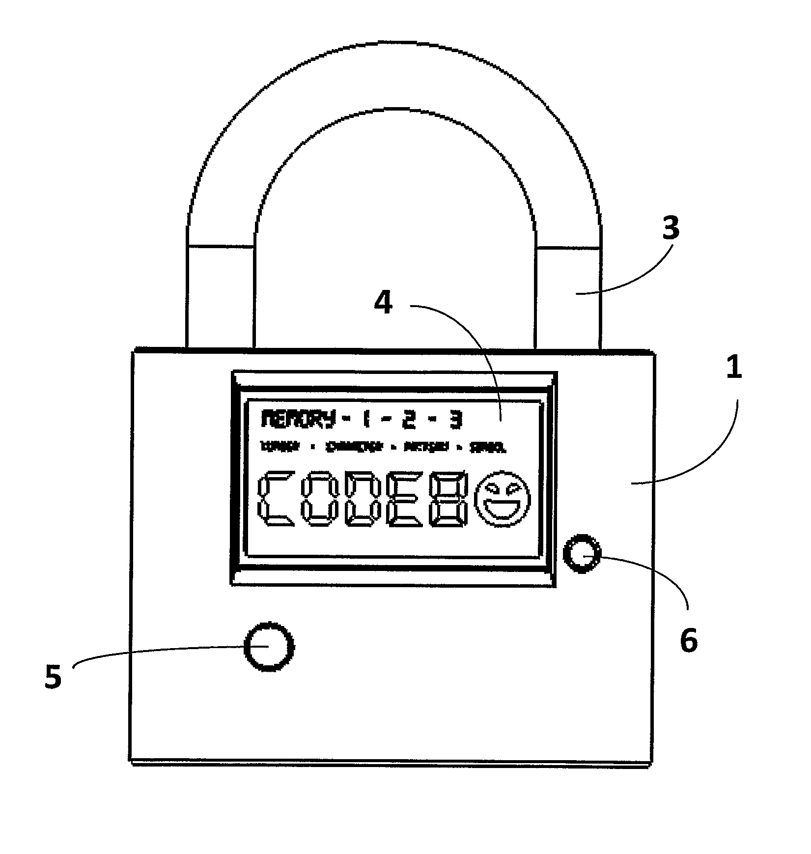
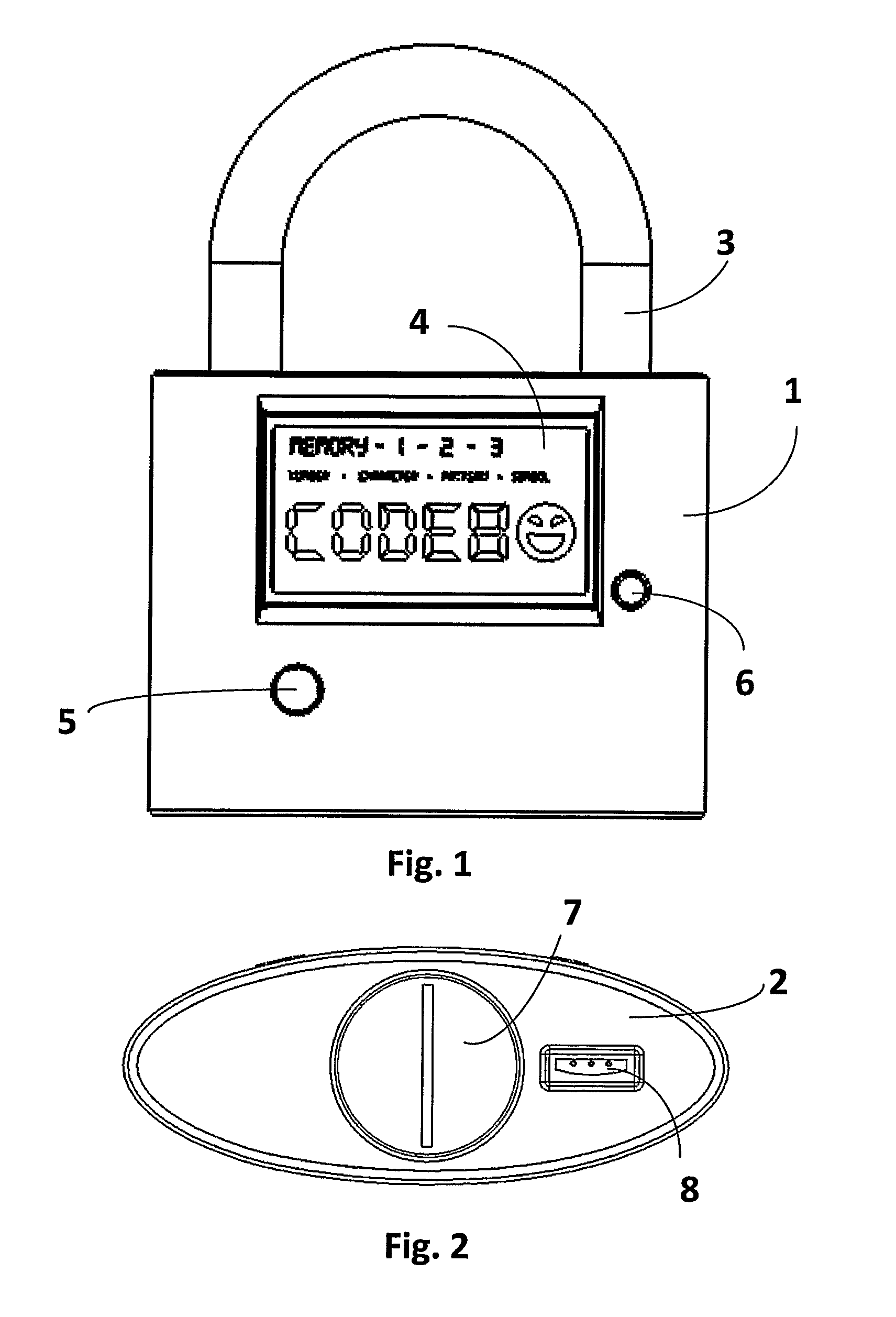
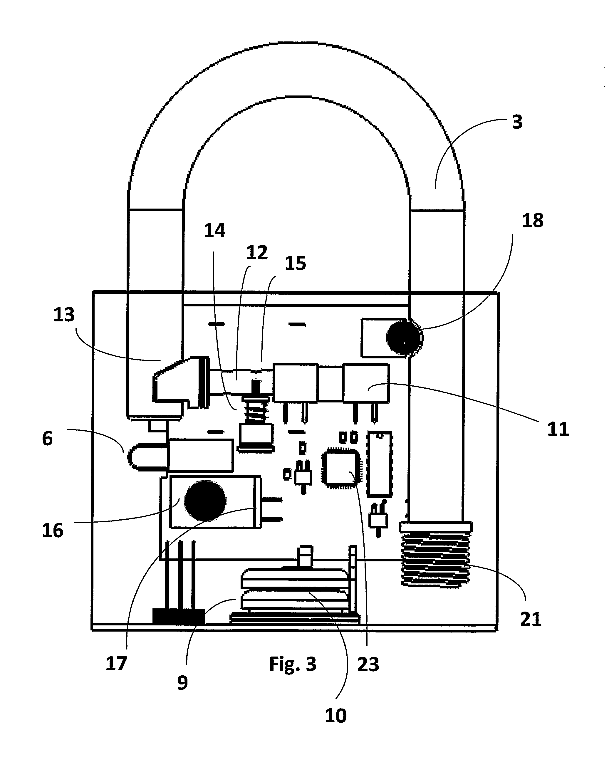
[0026]An embodiment of an electronic combination padlock can best be appreciated by referring to FIGS. 1 and 2. The electronic combination lock having a mixture of metal and plastic material to form a housing structure 1, preferably elongated, consists of metal plates 2 on the top and bottom of the housing 1 to reinforce the structure. The lock has a shackle-type locking bar 3 that is held lock in position within the housing 1. The front side of the housing 1 has a back-lighted touch screen Liquid Crystal Display (LCD) 4 either by color pixels or dot matrix which is capable of displaying combination of alphanumeric characters, symbols and patterns. It will be appreciated that LCD screen 4 includes both a touch sensor and an electronic display unit. The touch feature on the LCD screen 4 allows entering and controlling locking features. The LCD screen 4 is automatically turned off within a short duration to conserve battery power. In this preferred form described herein, the electroni...


PUM


Abstract

Disclosed herein is an electronic combination lock mainly characterized by miniature size and easy-to-use electronic identification access-gaining method that enables a vast variety and type of access codes for user setting and choice. Another battery operated electronic key unit, incorporated with programmed access code to provide as an alternative choice for locking, unlocking and backup power, can be used in conjunction with the electronic combination lock.

Description

BACKGROUND OF THE INVENTION[0001]Typical conventional locking devices, such as padlocks and luggage locks, require user to manually enter a sequence of numbers by adjusting multi-rotating dials inscribed with numeric digits to open a lock. This type of locking devices is commonly known as Combination Locks and they usually do not require a mechanical key. Instead users need to preset a combination digit code and remember this code when unlocking such locks. In contrast, existing electronic locks are usually designed with a bulky and relatively large numeric keypad for entering access codes. These keypads are not suitable for used in small size electronic combination locks.[0002]The invention is concerned with small size electronic combination locks. In particular, the invention relates to miniaturization and an easy-to-use electronic identification method for setting locking and unlocking combination access code of electronic combination locks such as padlocks, chain locks, luggage ...

Claims


Application Information

Patent Timeline
Patent Type & Authority Patents(United States)
IPC IPC(8): G05B19/00E05B67/00E05B47/06G07C9/00E05B15/00E05B47/00
CPCE05B67/00E05B47/06G07C9/0069E05B15/006E05B47/0012E05B2047/0016E05B2047/0065E05B2047/0094G07C2009/00634G07C2009/00793Y10T70/7068
Inventor LI, HUI HONG JIM KERY
Owner DIGIPAS TECH INC
Learn More