Acoustic absolute position encoder and method

a technology of absolute position and encoder, which is applied in the direction of directions, instruments, beacon systems using ultrasonic/sonic/infrasonic waves, etc. it can solve the problems of inconvenient use, low accuracy, and inability to detect absolute position, so as to achieve the effect of reducing the probability of errors in absolute position determination

Inactive Publication Date: 2015-09-01
SOLARCITY
View PDF14 Cites 2 Cited by
  • Summary
  • Abstract
  • Description
  • Claims
  • Application Information

AI Technical Summary

Benefits of technology

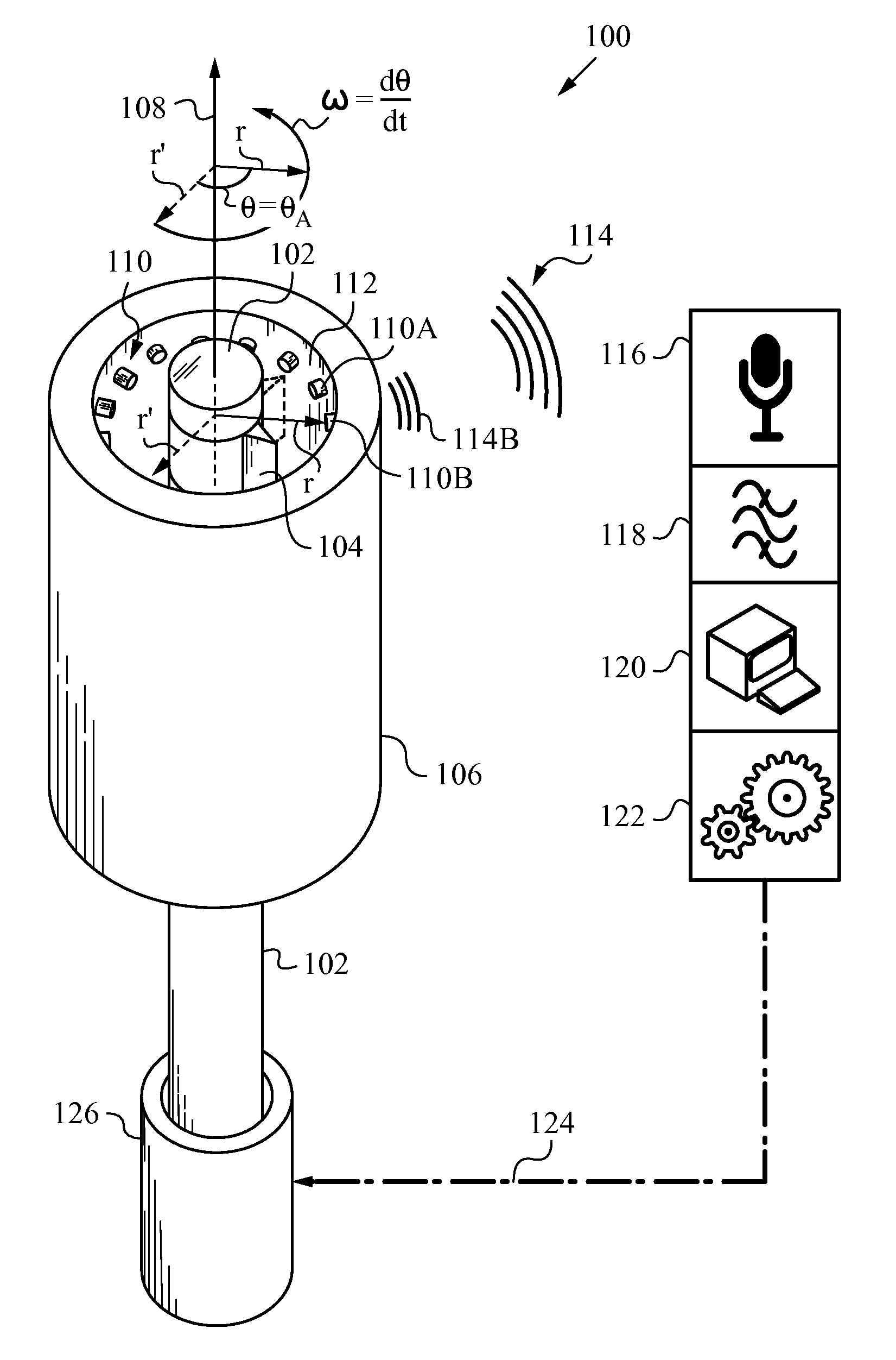
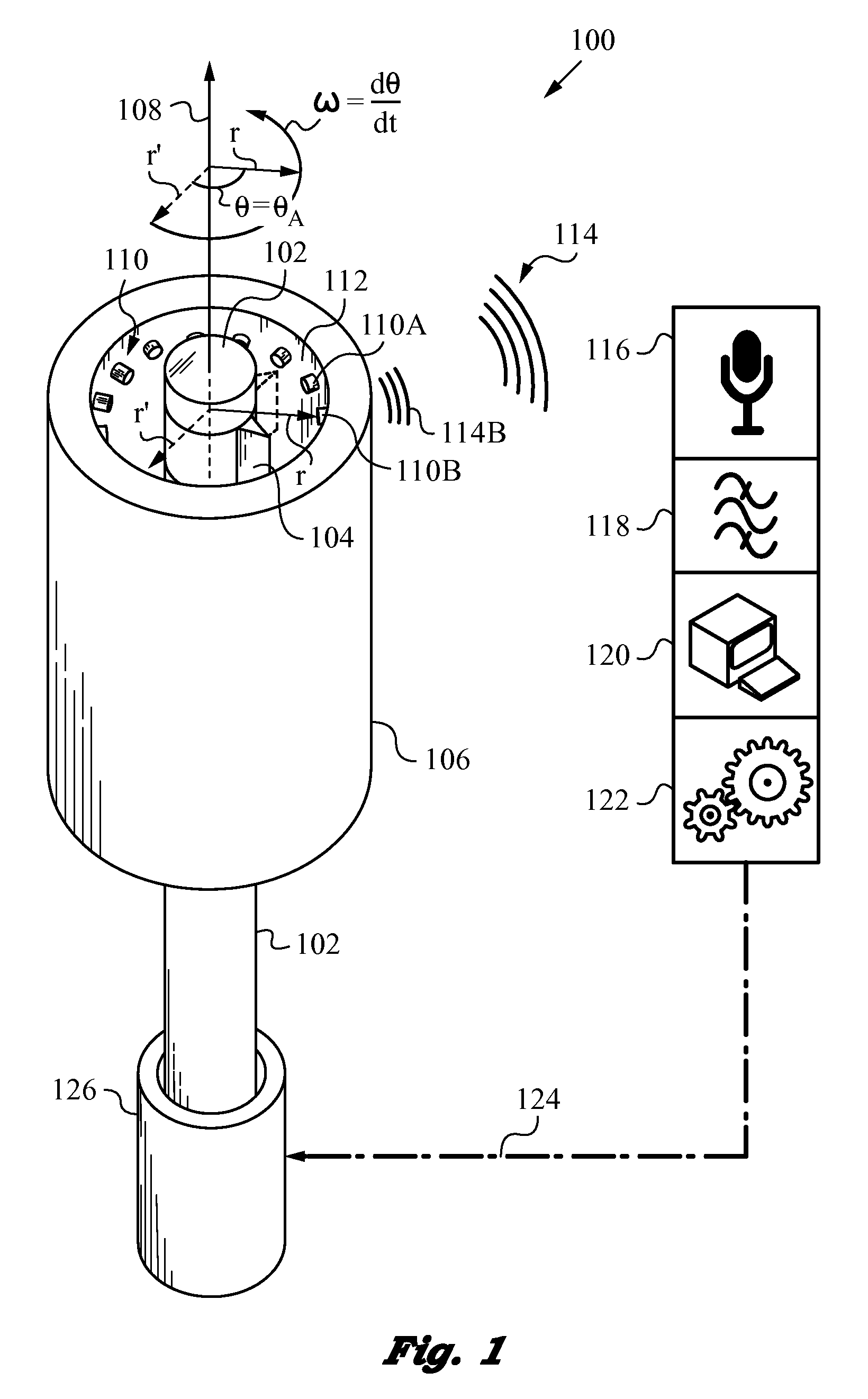
[0010]When a number of reed elements are present, they are preferably constructed to have differing tensile and / or geometric properties from each other. Thus, transient contact with the mechanical contacting portion as it moves over them generates different sound tones. At the very least, two different sound tones for two different reed elements should be used in this case. Of course, each reed element can be designed by proper choice of tensile properties (e.g., stiffness) and geometry (e.g., length) to generate its own unique sound tone. In addition, the sound tones can be coded in accordance with a suitable code, such as the Gray code, to ensure lower probability of errors in absolute position determination.
[0013]It is advantageous to deploy the absolute position encoder in conjunction with a feedback system. Thus, at least one mechanical structure can be adjusted in a closed-loop manner based on the absolute position measured acoustically in accordance with the invention.

Problems solved by technology

Even the least problematic contacts, such as brush-type contacts that establish electrical connections, are susceptible to wear and produce some mechanical resistance.
Thus, by now, encoders using contacts are not common and can only be found in low-speed applications such as manual volume or tuning controls (e.g., in a radio receiver).
As a result of this trend, there is a dearth of encoders relying on mechanical contact for providing position tracking solutions in applications where lower accuracy measurements of absolute angular and linear position are sufficient.
Unfortunately, such encoders are not presently available.

Method used


Image

  • Acoustic absolute position encoder and method
  • Acoustic absolute position encoder and method
  • Acoustic absolute position encoder and method

Examples


Embodiment Construction

[0028]The figures and the following description relate to preferred embodiments of the present invention by way of illustration only. It should be noted that from the following discussion, alternative embodiments of the structures and methods disclosed herein will be readily recognized as viable alternatives that may be employed without departing from the principles of the claimed invention.

[0029]Reference will now be made in detail to several embodiments of the present invention(s), examples of which are illustrated in the accompanying figures. It is noted that wherever practicable similar or like reference numbers may be used in the figures and may indicate similar or like functionality. The figures depict embodiments of the present invention for purposes of illustration only. One skilled in the art will readily recognize from the following description that alternative embodiments of the structures and methods illustrated herein may be employed without departing from the principle...


PUM


Abstract

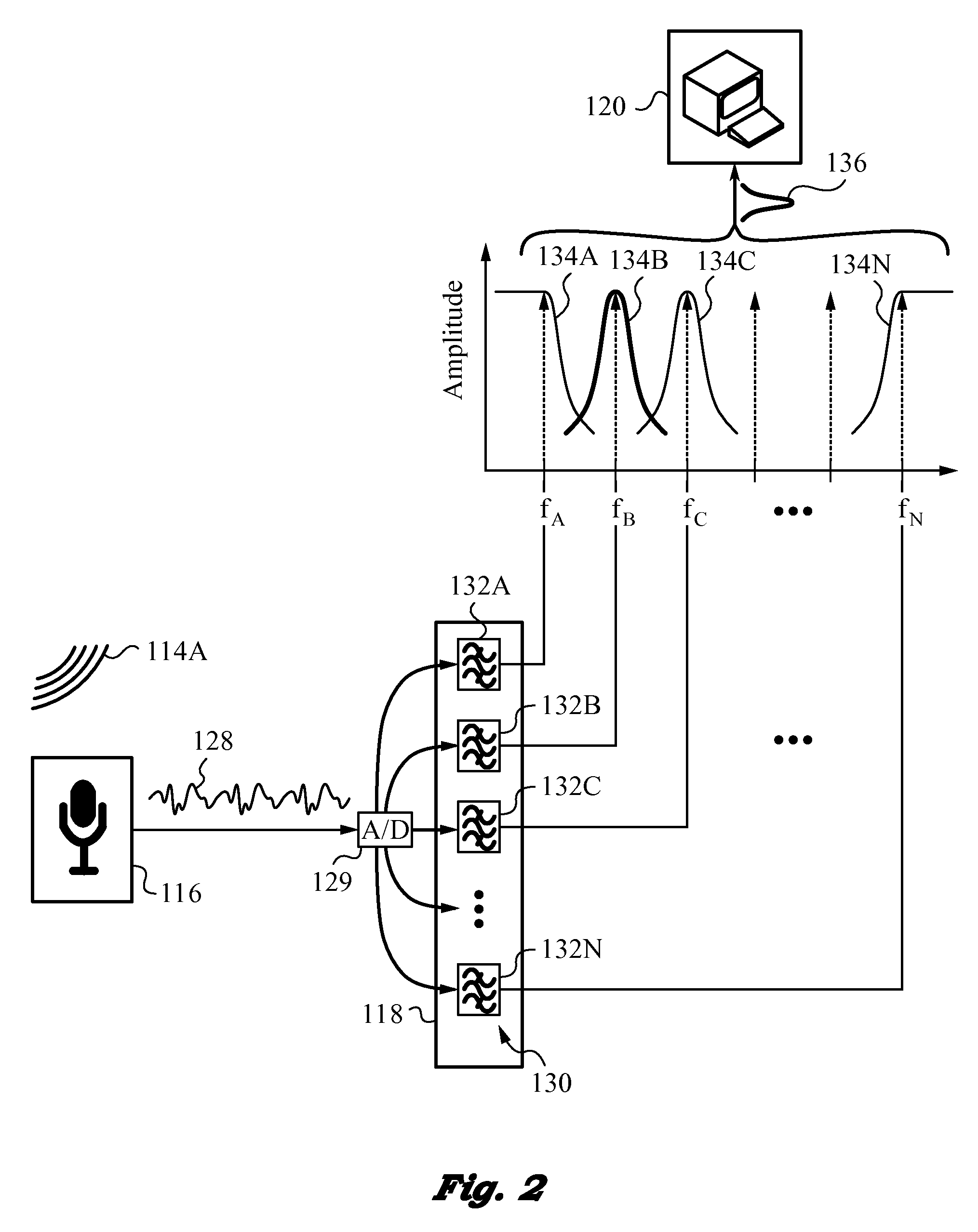
The present invention teaches acoustic absolute position encoders and methods for deploying the same. The encoder has a moving member with a mechanical contacting portion, and a stationary member associated with the moving member. Reed elements are mounted on the stationary member such that they are mechanically engaged by the contacting portion of the moving member as the latter moves linearly or rotates. The reed elements generate sound tones in response to transient contact with the contacting portion. A receiver receives the tones and an acoustic processing circuit determines the absolute position of the moving member based on the sound tones.

Description

FIELD OF THE INVENTION[0001]This application is related to linear and rotary encoders of the absolute type that track current position of a moving member with respect to a stationary member with the aid of acoustics.BACKGROUND ART[0002]Many mechanical and metrological applications involving linear and rotary movement of parts or articles transported by mechanical means require supervision. The supervision frequently requires knowledge about the absolute position of these parts or articles. To address this need, many types of absolute position encoders have been developed. In general, they include linear position encoders and rotary shaft encoders. The linear position encoders define absolute linear positions based on movement between a stationary reference and the linearly displaced part. Rotary shaft encoders of the absolute type define an absolute angular position in a similar manner, except for the fact that they track changes in an angle.[0003]Many of the prior art encoders, whe...

Claims


Application Information

Patent Timeline
Patent Type & Authority Patents(United States)
IPC IPC(8): G01S3/80G01S1/76
CPCG01S1/76
Inventor TRUJILLO, SALOMON J.
Owner SOLARCITY
Why Eureka
Try Eureka