Computer tomography unit with a data recording system

a computer and data recording technology, applied in the field of computed tomography units, can solve the problems of wear or dirt on the components themselves, and achieve the effect of rapid acquisition of the quality sta

Inactive Publication Date: 2007-03-13
SIEMENS HEALTHCARE GMBH
View PDF10 Cites 3 Cited by
  • Summary
  • Abstract
  • Description
  • Claims
  • Application Information

AI Technical Summary

Benefits of technology

[0004]An embodiment of the invention is based on an object of specifying a computed tomography unit in which the influence of changes such as aging, wear, dirt or other external disturbance influences on operation can be further reduced.
[0008]The computed tomography unit according to an embodiment of the invention, that is to say in which an evaluation device is integrated, has the advantage that, after a start event (which is produced, for example, by a person or by the computed tomography unit), the evaluation device operates automatically and without any further inputs (or at least without any further complex inputs) and thus allows a quality assessment to be carried out without a major time penalty. It is thus possible for a technician in the manufacturing phase, on the test panel or during a service visit to quickly make a statement on the current quality of the operation of the DAS or about the data transmission path, and to do this without having to connect an external test set for this purpose and having to link this by data connection to the CT unit. Once a statement about poor quality or a negative test result is available, the technician can if necessary carry out component replacements, readjustment of components and / or repair of components in the CT unit.
[0009]A further advantage is that, since there are no interactive actions, the probability of errors in carrying out the quality test is reduced, and the reproducibility of the test results is increased.
[0016]Since one or more predetermined parameters, that is to say parameters which are implemented in the evaluation device, are calculated using predetermined algorithms, that is to say a previously defined configuration process is carried out by the evaluation device or by its algorithms, and because the calculations are very largely carried out without any interaction with the user, the probability of errors in carrying out the quality test, and the reproducibility of the test results, are further improved, in terms of the latter also with respect to comparability of the test results which are obtained with different computer tomography units in one and the same series. The computed tomography units for this purpose are all equipped, for example, with the same evaluation device.

Problems solved by technology

Such changes may result from aging, wear or dirt on the components themselves, or else from external disturbance influences—which possibly occur only over the course of time.

Method used


Image

  • Computer tomography unit with a data recording system
  • Computer tomography unit with a data recording system
  • Computer tomography unit with a data recording system

Examples


Embodiment Construction

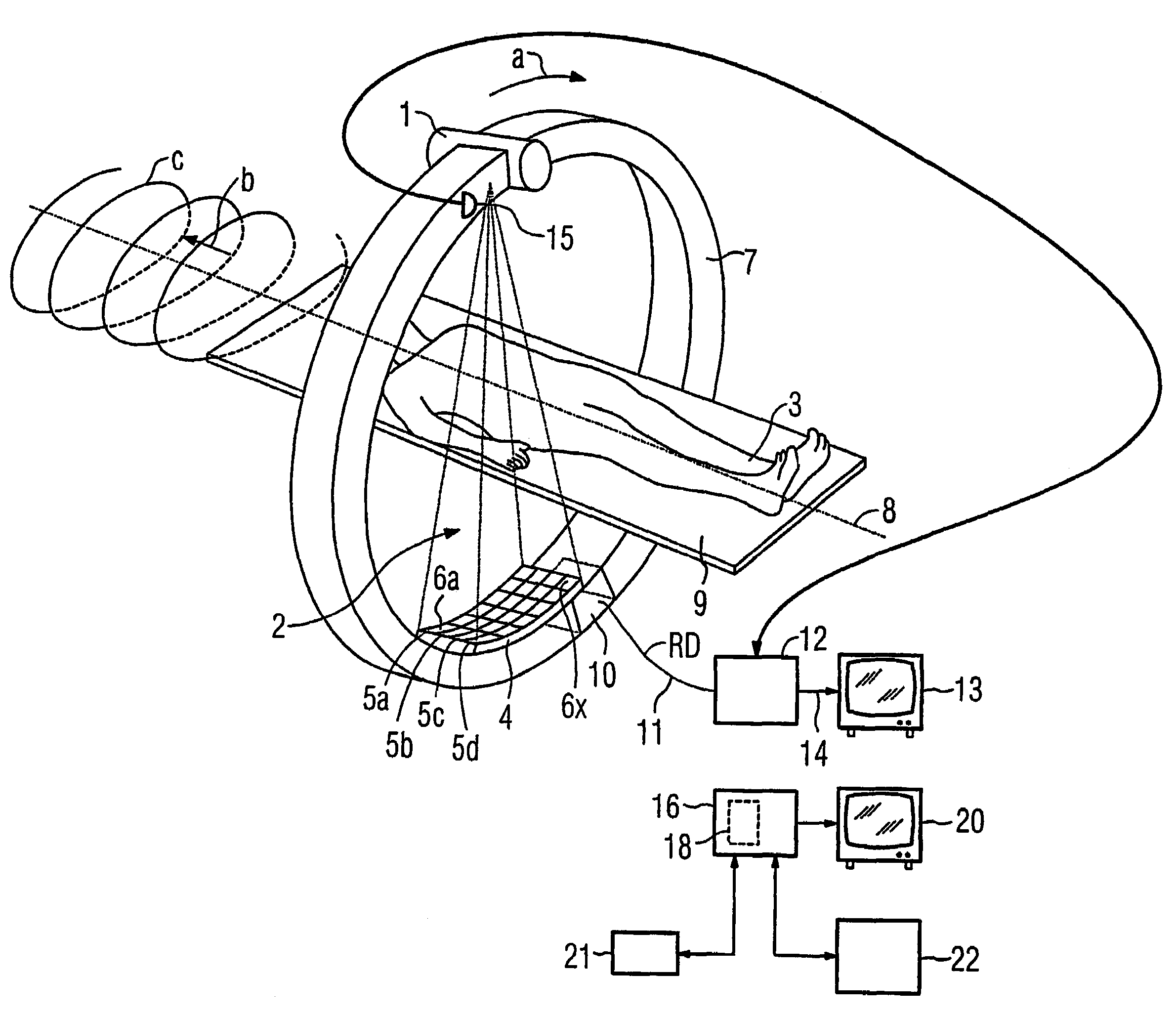
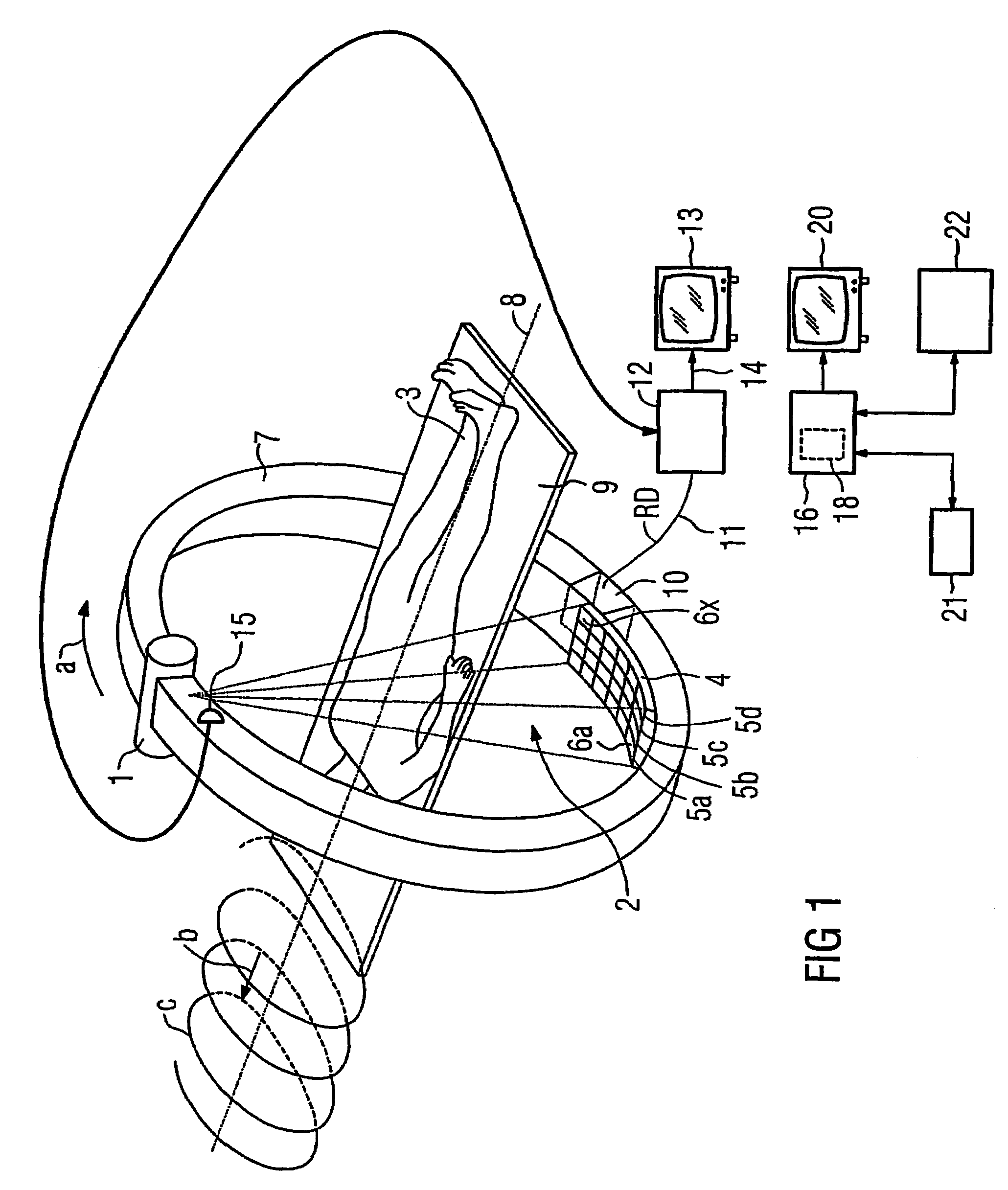
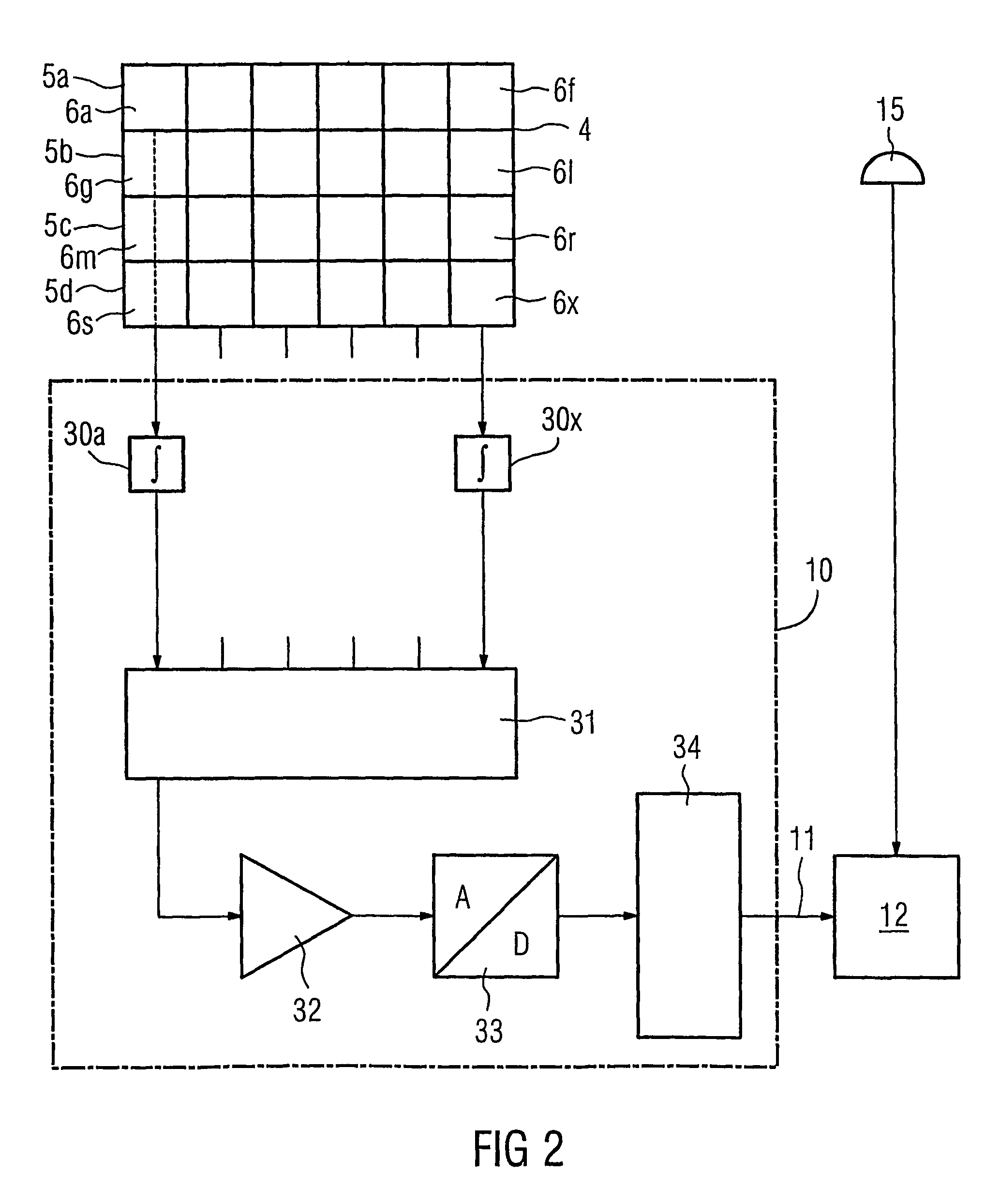
[0027]FIG. 1 shows, schematically, a computed tomography unit according to an embodiment of the invention with an X-ray beam source 1 which emits a pyramid-shaped X-ray beam 2, whose edge beams are illustrated by dashed-dotted lines in FIG. 1, which passes through an object being examined, for example a patient 3, and arrives at a radiation detector 4 which is equipped with a so-called UFC ceramic as a scintillator. The radiation detector 4 includes 4 or 16 detector rows 5a to 5d, which are arranged alongside one another and have a number (for example 672) of detector elements 6a to 6x arranged alongside one another.

[0028]The X-ray beam source 1 and the radiation detector 4 are arranged opposite one another on an annular scanning unit or gantry 7. The gantry 7 is mounted on a holding apparatus, which is not illustrated in FIG. 1, such that it can rotate with respect to a system axis 8 which runs through the center point of the annular gantry 7 (see the arrow a).

[0029]The patient 3 l...


PUM


Abstract

A computed tomography unit includes a radiation detector with several detector elements, a data recording system for reading the electrical signals generated by the detector elements and the processing thereof to give raw data may be supplied via a data transmission path. The computed tomography unit further includes an analytical device for the automatic determination of the quality of the data recording system and / or of the data transmission path and optionally the radiation detector in addition. The analytical unit in particular initiates a measurement for the generation of raw data, calculates at least one value for at least one parameter which permits a quality determination therefrom and displays an analytical result, which incorporates the calculated value, on a display device.

Description

[0001]This application is the national phase under 35 U.S.C. § 371 of PCT International Application No. PCT / DE03 / 01666 which has an International filing date of May 23, 2003, which designated the United States of America and which claims priority on German Patent Application number DE 102 25 613.6 filed Jun. 7, 2002, the entire contents of which are hereby incorporated herein by reference.FIELD OF THE INVENTION[0002]The invention generally relates to a computed tomography unit (CT unit) having a radiation receiver. Preferably the receiver has a number of detector elements, having a data acquisition system for reading the electrical signals which are produced by the detector elements and for processing them to form raw data, and having an image computer which is arranged downstream from the data acquisition system and to which the raw data can be supplied via a data transmission path.BACKGROUND OF THE INVENTION[0003]U.S. Pat. No. 6,264,365 B1 describes the monitoring of CT data, whic...

Claims


Application Information

Patent Timeline
Patent Type & Authority Patents(United States)
IPC IPC(8): G06F11/30A61B6/00A61B6/03
CPCA61B6/583A61B6/03A61B6/56
Inventor HEIN, PETERSIMON, JURGEN
Owner SIEMENS HEALTHCARE GMBH
Why Eureka
Try Eureka