Method for the load-free opening of a separating clutch

a technology of separating clutch and load-free opening, which is applied in the direction of mechanical actuated clutches, instruments, mechanical apparatus, etc., can solve the problems of difficult operation state production, and achieve the effect of reliable and rapid manner

Active Publication Date: 2015-09-08
ROBERT BOSCH GMBH
View PDF27 Cites 0 Cited by
  • Summary
  • Abstract
  • Description
  • Claims
  • Application Information

AI Technical Summary

Benefits of technology

[0003]Therefore, there may be need for a better method for opening the clutch, in which a torque-free operating state of the clutch is produced in reliable and rapid manner.
[0005]In other words, in accordance with an example embodiment of the present invention, an adjustment is provided of the torque in the known range of the system by means of a drive-side deceleration, and a subsequent drive-side acceleration, so that the torque is increased over time by the drive side, starting from the known range of the system, until it generally matches the torque on the output side. This enables a load-free opening of the clutch.
[0012]As soon as the amount of the torque applied at the separating clutch lies within predefined limit values, the separating clutch is opened. In other words, as soon as the difference of the output-side and the drive-side torque lies within specific threshold values, the clutch is essentially in a load-free state and is able to be opened in reliable manner. The limit value may be set to 4 Newton-meter (Nm), for example. This makes it possible to ensure driving comfort, for instance when opening a clutch in a vehicle, because the lower the limit values are set, the less noticeable and jerk-free the clutch is able to be opened.
[0015]The example method according to the present invention, the example control unit and the example computer program element are able to ensure that the clutch is opened in a robust, reliable and safe manner.

Problems solved by technology

However, it is difficult to produce the operating state that ensures a torque-free state at the coupling point without additional measurements and calculations.

Method used


Image

  • Method for the load-free opening of a separating clutch
  • Method for the load-free opening of a separating clutch
  • Method for the load-free opening of a separating clutch

Examples


Embodiment Construction

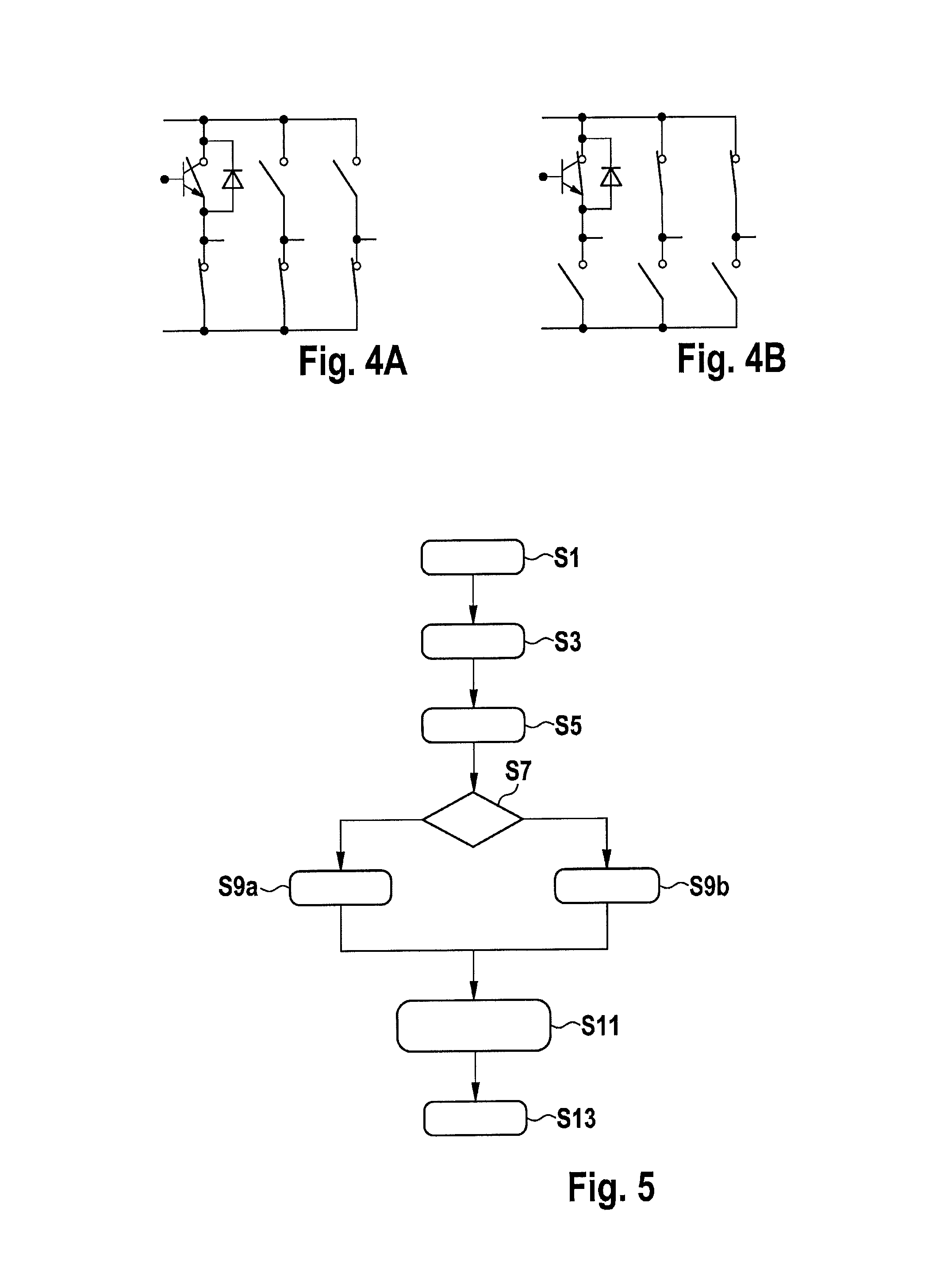
[0022]All of the figures are merely schematic representations of the example method according to the present invention or its method steps. Clearances and size relationships, in particular, are not reflected true to scale in the figures. Corresponding elements are provided with the same reference numerals in the different figures.

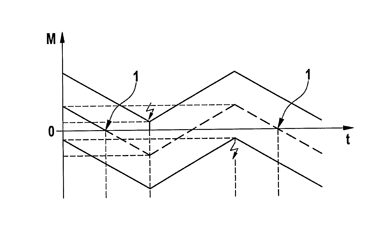
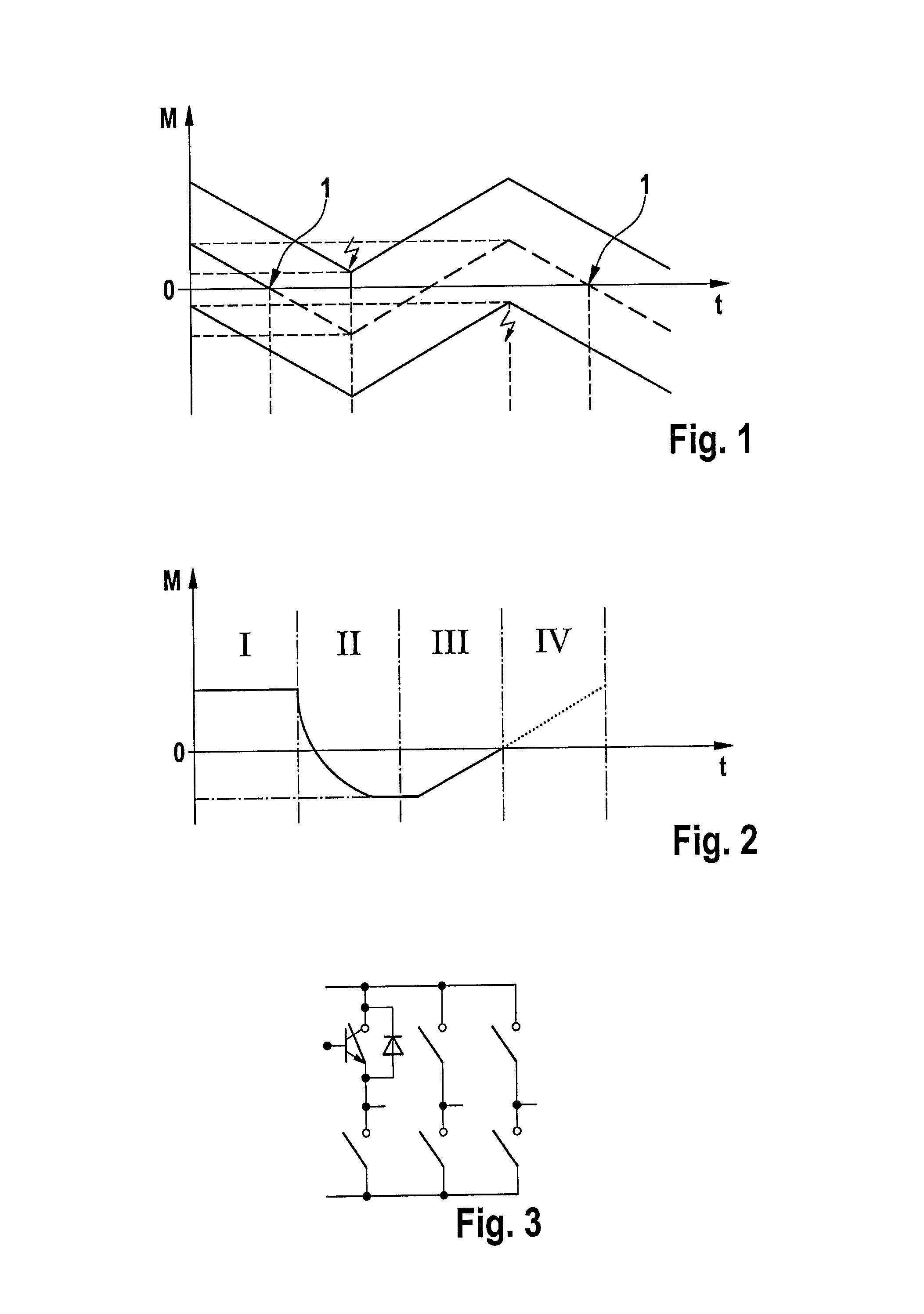
[0023]FIG. 1 illustrates the time characteristic of a torque when attempting to produce a torque-free state at a separating clutch. In the illustrated coordinate system, time t, in milliseconds, has been plotted on the abscissa, and torque M, in Newton meters, has been plotted on the ordinate.

[0024]A virtual absence of torque must be produced at the coupling point to open the clutch. To do so, an attempt may be made to compensate the friction losses. If this is unsuccessful, the alternative consists of attempting to set a torque at the coupling point that is slightly higher than zero, using an electric drive, for example, and then to run through a torque ra...


PUM


Abstract

A method is provided for the load-free opening of a separating clutch. The method includes the following steps: receiving a signal for disengaging the clutch; applying a negative torque at the separating clutch using a drive machine; applying a positive, predefined torque at the separating clutch using the drive machine; and opening the separating clutch as soon as the amount of the torque applied at the separating clutch lies within predefined limit values. In other words, a torque in the known range of the system is set via a drive-side deceleration. Then, a drive-side acceleration takes place, so that the torque is increased on the drive side, starting from the known range of the system, until it generally matches the torque on the output side. This enables a load-free opening of the clutch.

Description

BACKGROUND INFORMATION[0001]A clutch such as a claw clutch is used in electric and hybrid vehicles, especially in the case of electrically driven axles, for the purpose of separating the electric drive from the wheels to be driven.[0002]The claw clutch can be opened only if no torque, or only a very small torque, is applied at the coupling point. This requirement is able to be satisfied in that losses produced by friction, for instance, are compensated, for example via the electric drive. However, it is difficult to produce the operating state that ensures a torque-free state at the coupling point without additional measurements and calculations.SUMMARY[0003]Therefore, there may be need for a better method for opening the clutch, in which a torque-free operating state of the clutch is produced in reliable and rapid manner.[0004]Features, details and possible advantages of a device according to one specific embodiment of the present invention are described in detail below. According ...

Claims


Application Information

Patent Timeline
Patent Type & Authority Patents(United States)
IPC IPC(8): B60W10/02F16D48/06B60W10/08B60W30/18
CPCF16D48/06B60W10/02B60W10/08B60W30/18F16D2500/10412F16D2500/10462F16D2500/1066F16D2500/30412F16D2500/30415F16D2500/30421F16D2500/3166F16D2500/7041
Inventor MERKEL, TINOPETER, MARKUS
Owner ROBERT BOSCH GMBH
Why Eureka
Try Eureka