Speed reducer

a technology of speed reducer and reducer, which is applied in the direction of friction gearing, toothed gearing, bearing and roller, etc., can solve the problems of reducing the gap 20/b> of the roller, and the inability to rotate at a constant speed, so as to reduce the vibration stabilize the quality of the speed reducer

Active Publication Date: 2015-09-08
NTN CORP
View PDF10 Cites 0 Cited by
  • Summary
  • Abstract
  • Description
  • Claims
  • Application Information

AI Technical Summary

Benefits of technology

[0014]An object of the present invention is to reduce vibration of a speed reducer and stabilize the quality of the speed reducer, by setting the roller gaps within an optimum range.
[0016]The roller gaps refer to the gaps one of which is shown in FIG. 5 at 20. By setting the roller gaps within the range of 0 to 20 μm, as is apparent from the test results of various characteristics shown in FIG. 6, it is possible to reduce vibration of the speed reducer and stabilize the quality of the speed reducer.
[0019]According to the speed reducer of the present invention, since the roller gaps defined between the rollers and tooth bottoms of the internal gear are adjusted within a range of 0 to 20 μm by measuring beforehand the root radius of the internal gear, the radius of the circumcircle of the rolling bearing, the circumcircle having a center lying on a center axis of the input shaft, and the outer diameter of the rollers, it is possible to reduce vibration of the speed reducer and stabilize the quality of the speed reducer.

Problems solved by technology

Component parts forming the above-described roller type speed reducer, such as the internal gear, eccentric disks, rolling bearings and rollers, have manufacturing errors.
Conventional speed reducers are manufactured by simply assembling together these component parts, which have manufacturing errors, so that roller gaps tend to vary from one speed reducer to another, and thus their qualities also tend to vary.
Thus, the roller gaps 20 may be too large in some speed reducers.
Efficiency: If some roller gaps are too large and other gaps are too small, the speed reducer cannot rotate at a constant speed.
Also, torque loss is large where roller gaps are small, which reduces efficiency.
Life: Excessive surface pressures are generated between the contact portions of a roller and the radially inner surface of the internal gear or between the roller and the outer race of the rolling bearing when the roller passes through an excessively small roller gap, which could result in premature peeling.
Vibration: Behaviors of the rollers become unstable when they pass through excessively small roller gaps, producing vibration.

Method used


Image

  • Speed reducer
  • Speed reducer
  • Speed reducer

Examples


Embodiment Construction

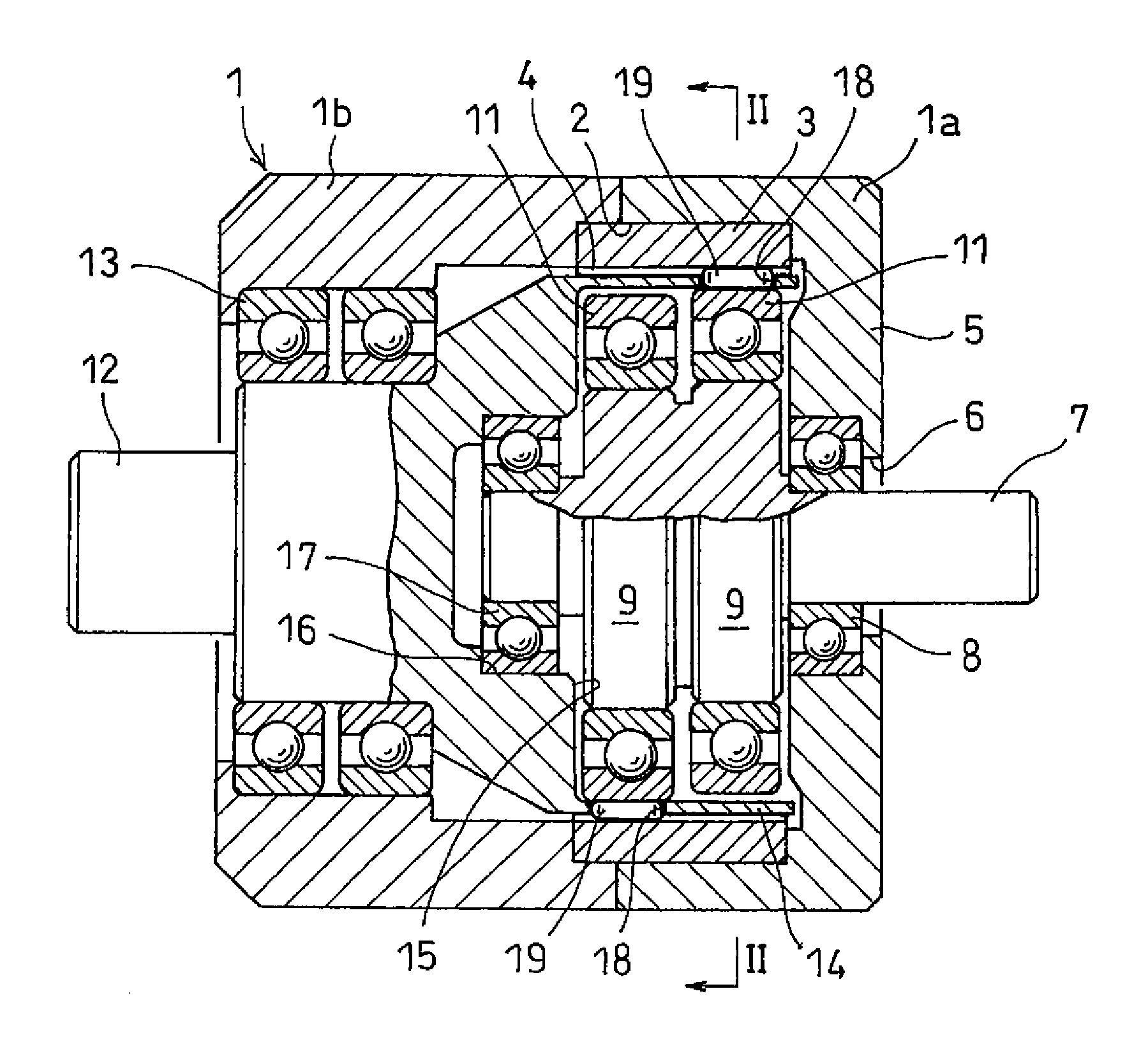
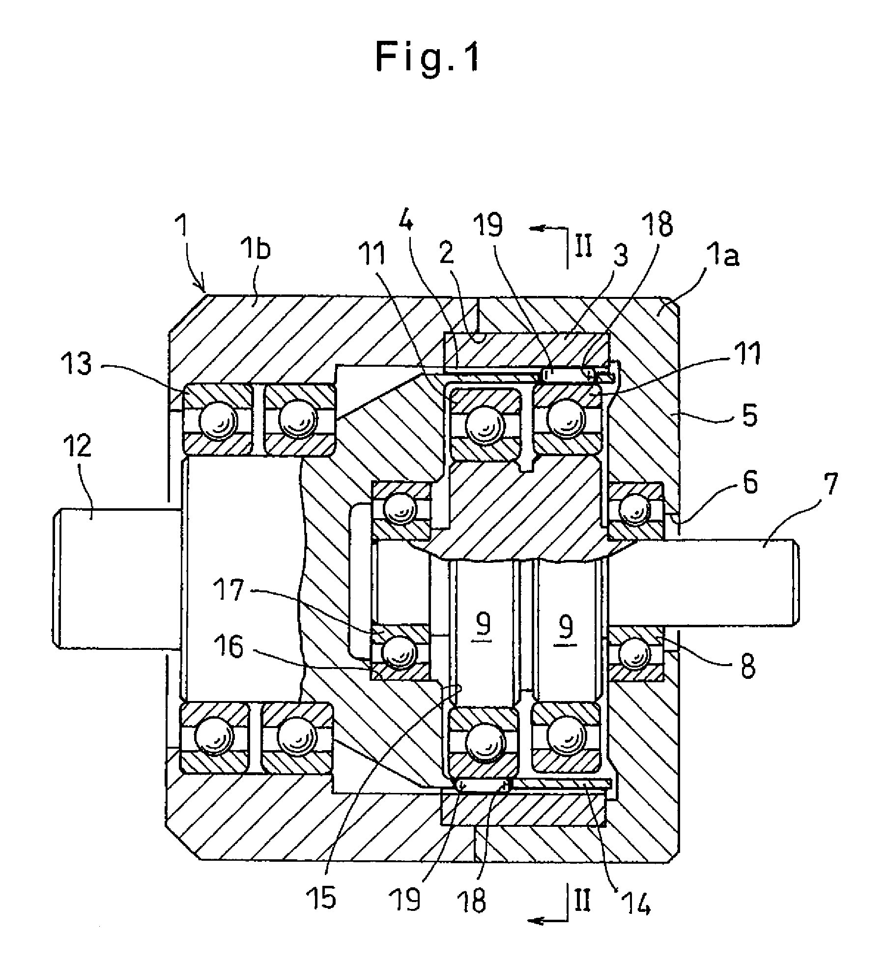
[0026]Referring now to the drawings, the speed reducer embodying the present invention includes a cylindrical housing 1 (FIG. 1). The housing 1 is axially split into first and second split housing portions 1a and 1b.

[0027]The first and second split housing portions 1a and 1b are joined together by tightening bolts (not shown). A large-diameter recess 2 is formed in the radially inner surfaces of the first and second split housing portions 1a and 1b near the abutment ends thereof to extend across the abutment ends.

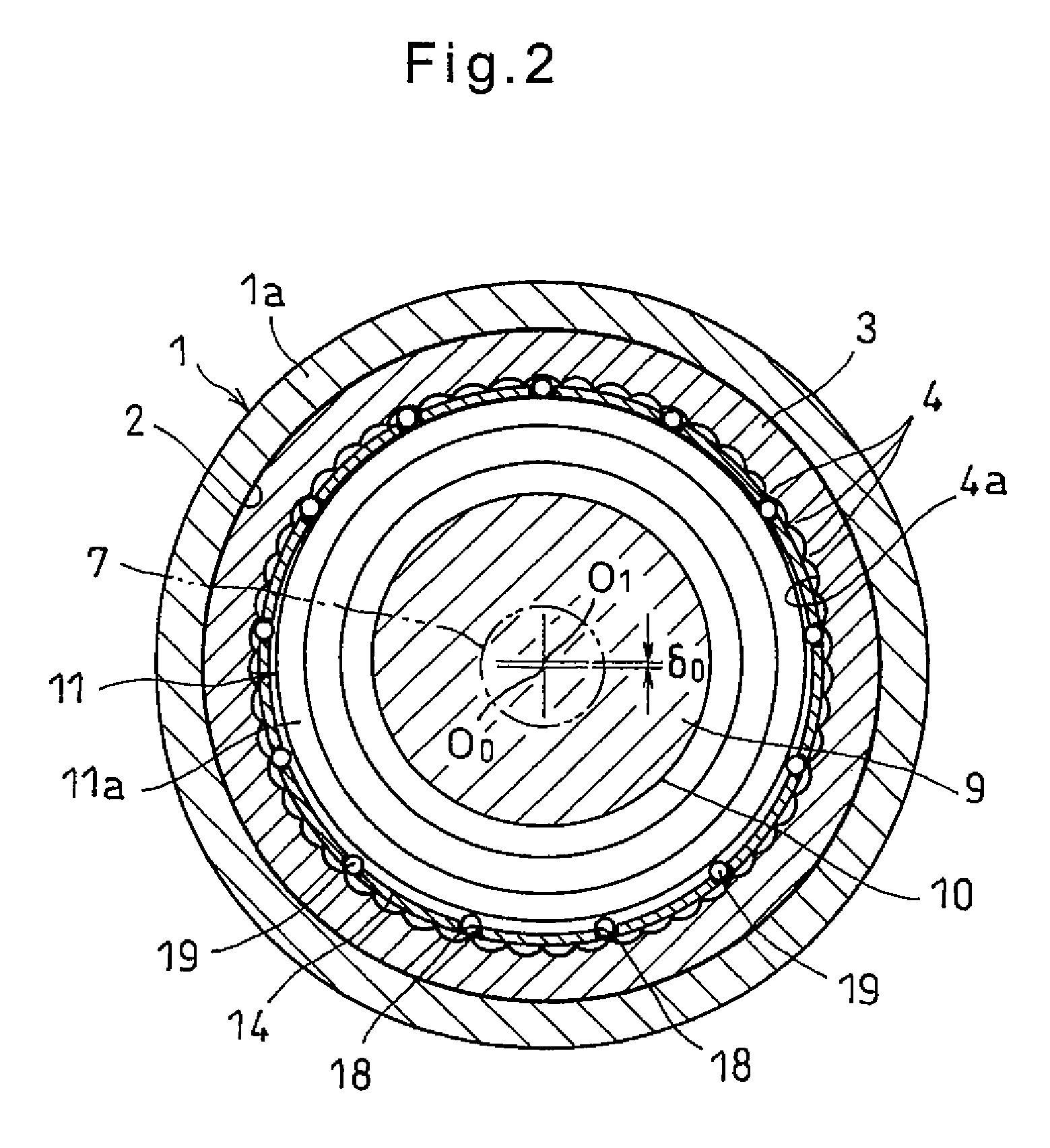
[0028]As shown in FIGS. 1 and 2, an internal gear 3 having a plurality of teeth 4 on the inner periphery thereof is press-fitted in the large-diameter recess 2.

[0029]As shown in FIG. 1, the first split housing portion 1a has an end wall 5 closing one end of the housing portion 1a. An input shaft 7 extends through a shaft inserting hole 6 formed in the center of the end wall 5. The input shaft 7 is rotatably supported by a bearing 8 mounted in the shaft inserting hole 6 so ...


PUM


Abstract

A speed reducer includes an internal gear, an input shaft coaxial with the internal gear, and an eccentric disk on the input shaft and rotatable inside the internal gear. A cage, at an end of an output shaft, coaxial with the input shaft, and rotatable between the internal gear and the eccentric disk has pockets fewer in number than the internal gear's internal teeth. Rollers are received in the respective pockets such that when the input shaft rotates once, the rollers circumferentially move by a distance equal to one internal tooth width, causing the output shaft to be rotated at a reduced speed. The root radius of the internal gear, the radius of the circumcircle of the rolling bearing, and the outer diameter of the rollers are determined such that roller gaps defined between the rollers and the tooth bottoms of the internal gear are controlled to reduce vibration.

Description

TECHNICAL FIELD[0001]This invention relates to a speed reducer of the type including rollers adapted to be brought into meshing engagement with the internal teeth of an internal gear one after another, of which the rollers are fewer in number than the internal teeth of the internal gear.BACKGROUND ART[0002]JP Patent Publication 62-93565A discloses one of such roller type speed reducers. The roller type speed reducer disclosed in JP Patent Publication 62-93565A includes an input shaft and an output shaft that are arranged coaxial with each other with their ends facing each other. A housing covers the opposed ends of the input and output shafts, and supports an internal gear having curved internal teeth on the inner periphery. Two eccentric disks are mounted, axially spaced apart from each other, on the end portion of the input shaft so as to be rotatable inside the internal gear. A cage is provided at the end of the output shaft facing the input shaft so as to be disposed between the...

Claims


Application Information

Patent Timeline
Patent Type & Authority Patents(United States)
IPC IPC(8): F16H13/08F16H3/62F16H3/48F16H57/08F16H1/32
CPCF16H1/321F16H1/32F16H3/48F16H3/62F16H13/08F16H57/0006F16H2057/0081
Inventor AKIYOSHI, KOJISATO, KOJINAKAKOJI, MASAFUMI
Owner NTN CORP
Why Eureka
Try Eureka