
Laparoscopic instrument

a technology of laparoscopic instruments and instruments, applied in the field of laparoscopic medical instruments, can solve the problems of limited range of motion in the surgical site, poor depth perception by the surgeon, and the inability of laparoscopic tools to mov

Inactive Publication Date: 2015-09-15
ENDOPLUS +1
View PDF23 Cites 789 Cited by
  • Summary
  • Abstract
  • Description
  • Claims
  • Application Information

AI Technical Summary

Benefits of technology

[0008]An advantage of the present laparoscopic instrument is that the device may be thoroughly cleaned and reused.
[0016]Still another advantage of the present laparoscopic instrument is that the handle assembly remains contained within itself when disassembled for the purpose of cleaning, sterilization, or changing inserts.

Problems solved by technology

Disadvantages of a laparoscopic procedure include: limited mobility of range of motion in the surgical site, poor depth perception by the surgeon, and often laparoscopic tools do not move in the same direction as the surgeons hands.
However, these patents fail to provide a laparoscopic instrument as defined in the present application.
More specifically, these patents fail to define a laparoscopic instrument which has a flush port on a top end for cleaning, a locking mechanism on the handle, a viewing channel on the back end for visually verifying if the instrument is clean and for passing a brush through the interior lumen of the entire device for cleaning, a handle mechanism which is self contained, a keeper mechanism which both holds the self contained handle in a position which accommodates cleaning and sterilization and holds the self contained handle in a position which facilitates use during surgery, and an opening on the side for confirming a movable actuating rod is secured within the handle portion.

Method used


Image

  • Laparoscopic instrument
  • Laparoscopic instrument
  • Laparoscopic instrument

Examples


Embodiment Construction

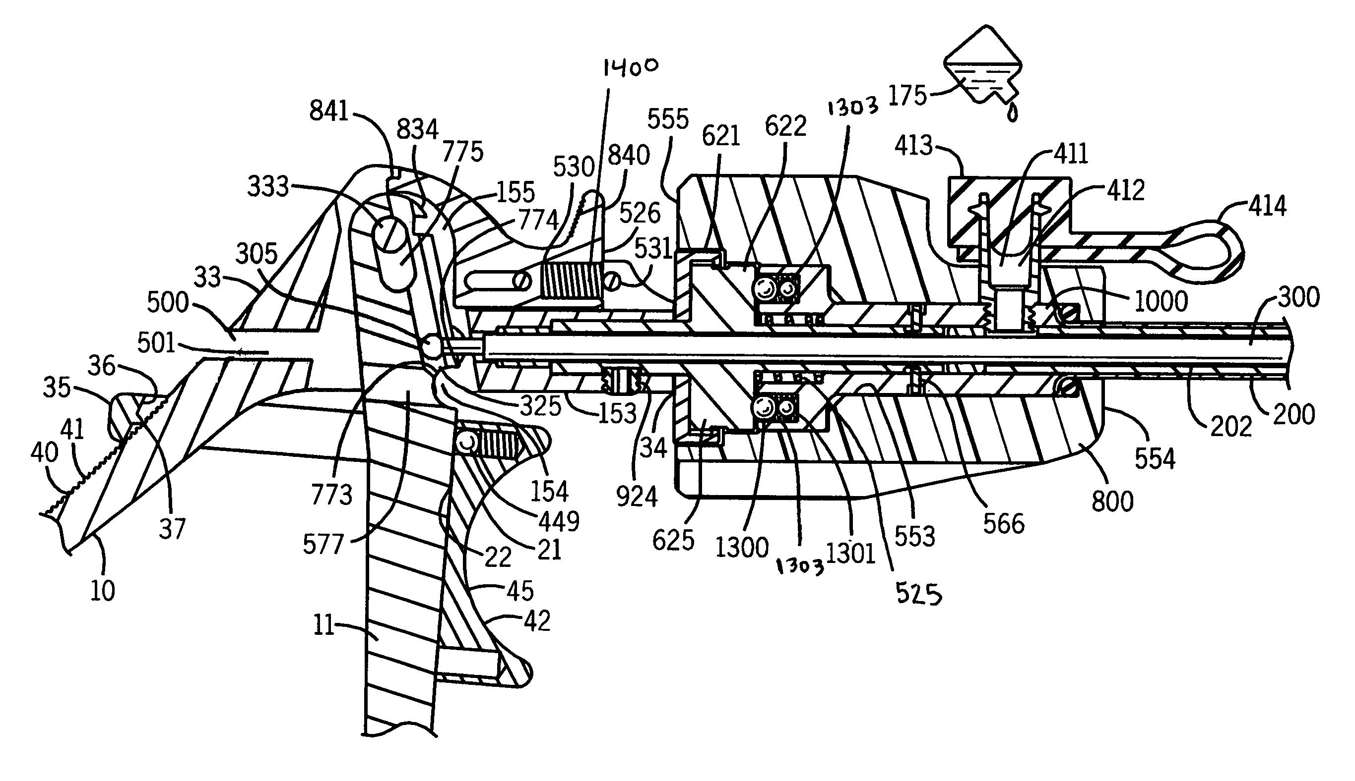
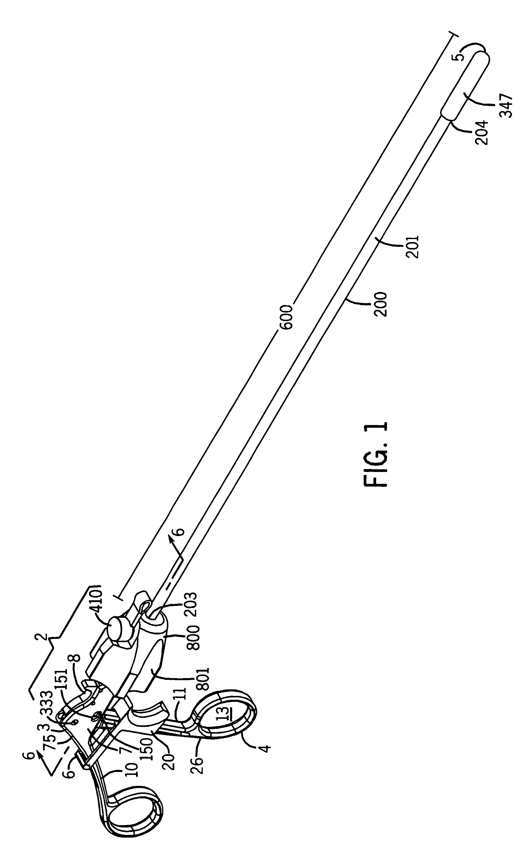
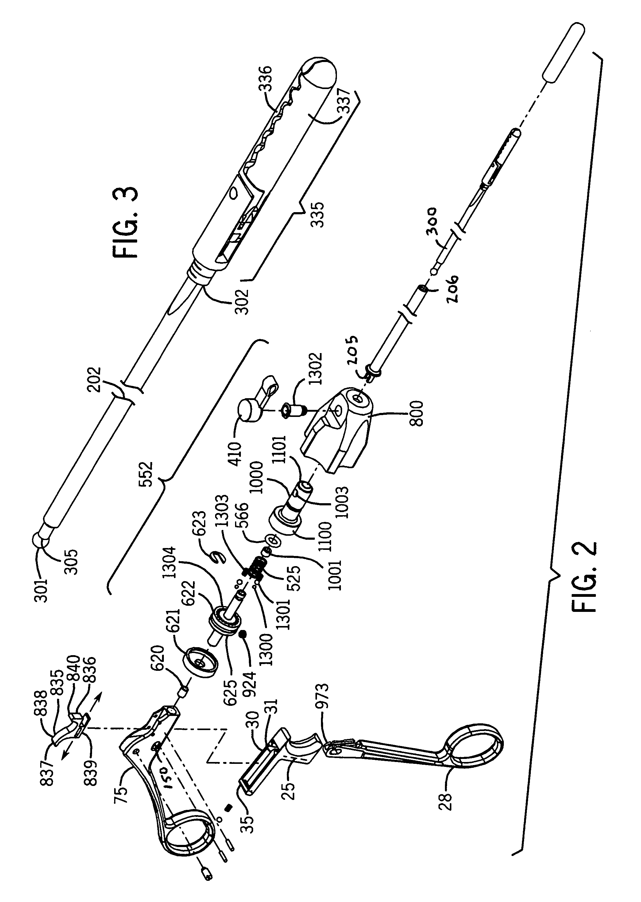
[0024]The present device relates to a laparoscopic medical instrument, particularly those used for minimally invasive surgery. The instrument has a movable and a stationary handle portion and an extended shaft assembly with a removable actuating rod. An opening on the side of the stationary handle portion allows a user to visually confirm the removable actuating rod is locked into place within the movable handle portion. An opening in the back of the stationary handle portion allows for cleaning and visual inspection of the interior of the barrel portion once the rod is removed. The actuating rod has a grasping mechanism for performing work during surgery. A flush port is located near the distal end of the stationary handle portion.

[0025]Referring now to FIG. 1, a laparoscopic instrument 1 is provided which is suitable for medical purposes. The laparoscopic instrument 1 may have a handle portion 2 and a shaft assembly portion 200 having a length 600. The laparoscopic instrument 1 ma...


PUM


Abstract

The present device relates to a laparoscopic medical instrument, particularly those used for minimally invasive surgery. The instrument has a movable and a stationary handle portion and an extended shaft assembly with a removable actuating rod. An opening on the side of the stationary handle portion allows a user to visually confirm the removable actuating rod is locked into place within the movable handle portion. An opening in the back of the stationary handle portion allows for cleaning and visual inspection of the interior of the shaft assembly portion once the rod is removed. The actuating rod has a grasping mechanism for performing work during surgery. A flush port is located near the distal end of the stationary handle portion.

Description

REFERENCE TO RELATED APPLICATIONS[0001]The present application is based on U.S. provisional patent application No. 61 / 517,177 filed Apr. 15, 2011, the entire contents of which are incorporated by reference. Applicant claims the priority benefit of the 61 / 517,177 application.BACKGROUND OF THE INVENTION[0002]The present device relates to a laparoscopic medical instrument, particularly those used for minimally invasive surgery. The instrument has a movable and a stationary handle portion and an extended shaft assembly with a removable actuating rod. An opening on the side of the stationary handle portion allows a user to visually confirm the removable actuating rod is locked into place within the movable handle portion. An opening in the back of the stationary handle portion allows for cleaning and visual inspection of the interior of the shaft assembly portion once the rod is removed. When disassembled for the purpose of cleaning or for changing inserts, the handle assembly remains co...

Claims


Application Information

Patent Timeline
Patent Type & Authority Patents(United States)
IPC IPC(8): A61B17/00A61B17/29A61B19/00
CPCA61B17/29A61B19/34A61B2017/292A61B2017/2946A61B2019/4868A61B90/70A61B2090/0813
Inventor MATTHEW, GUDEMAN
Owner ENDOPLUS
Learn More