

Liquid discharging head
a liquid discharging head and liquid technology, applied in the direction of printing, inking apparatus, etc., can solve the problems of damage to the surface of the electrothermal conversion element, air bubbles are not readily split, and the surrounding air is damaged
- Summary
- Abstract
- Description
- Claims
- Application Information
AI Technical Summary
Benefits of technology
Problems solved by technology
Method used
Image

Examples
first embodiment
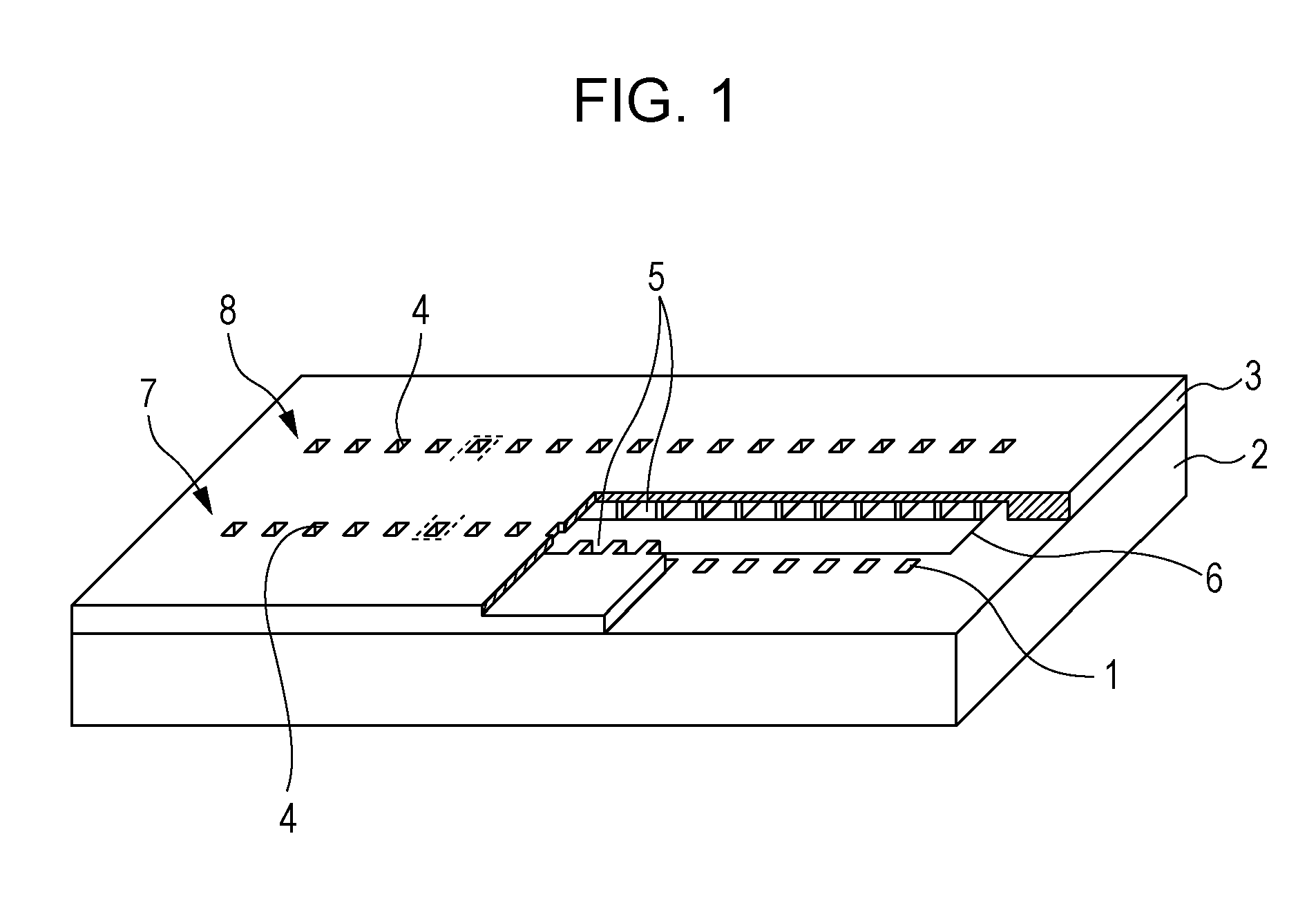
[0020]FIG. 1 is a perspective view illustrating a state in which a portion of a liquid discharging head according to the first embodiment of the present invention has been cut away. The liquid discharging head is configured of a laminate of an element substrate 2, and a flow path forming substrate 3 joined onto the principal surface of the element substrate 2.
[0021]The element substrate 2 is formed of glass, ceramics, resin, metal, or the like. A plurality of electrothermal conversion elements (energy generating elements) 1 configured to generate thermal energy are arrayed on the principal surface of the element substrate 2, and the sizes of these electrothermal conversion elements 1 are 24.4 μm×24.8 μm. In addition to these, provided to the principal surface of the element substrate 2 are a supply port 6 configured to supply ink to a later-described supply path 5, an electrode, which is not illustrated, configured to apply voltage to each of the electrothermal conversion elements 1...
second embodiment
[0038]A liquid discharging head according to a second embodiment of the present invention is also configured of, as illustrated in FIG. 1, a laminate of an element substrate 2 including a plurality of electrothermal conversion elements 1, and a flow path forming substrate 3 joined onto the principal surface of the element substrate 2 and having a first discharging port row 7 and a second discharging port row 8.
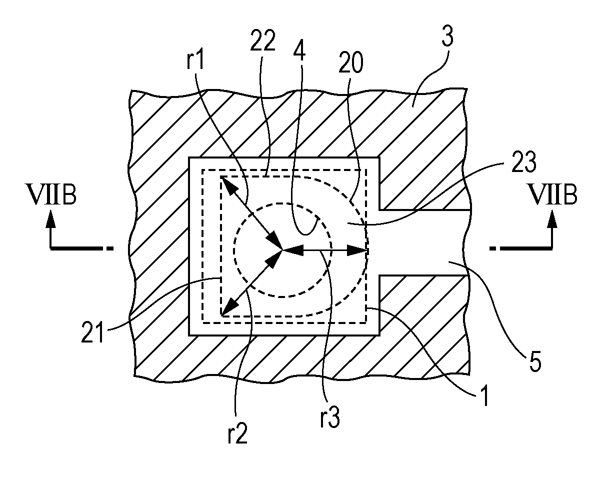
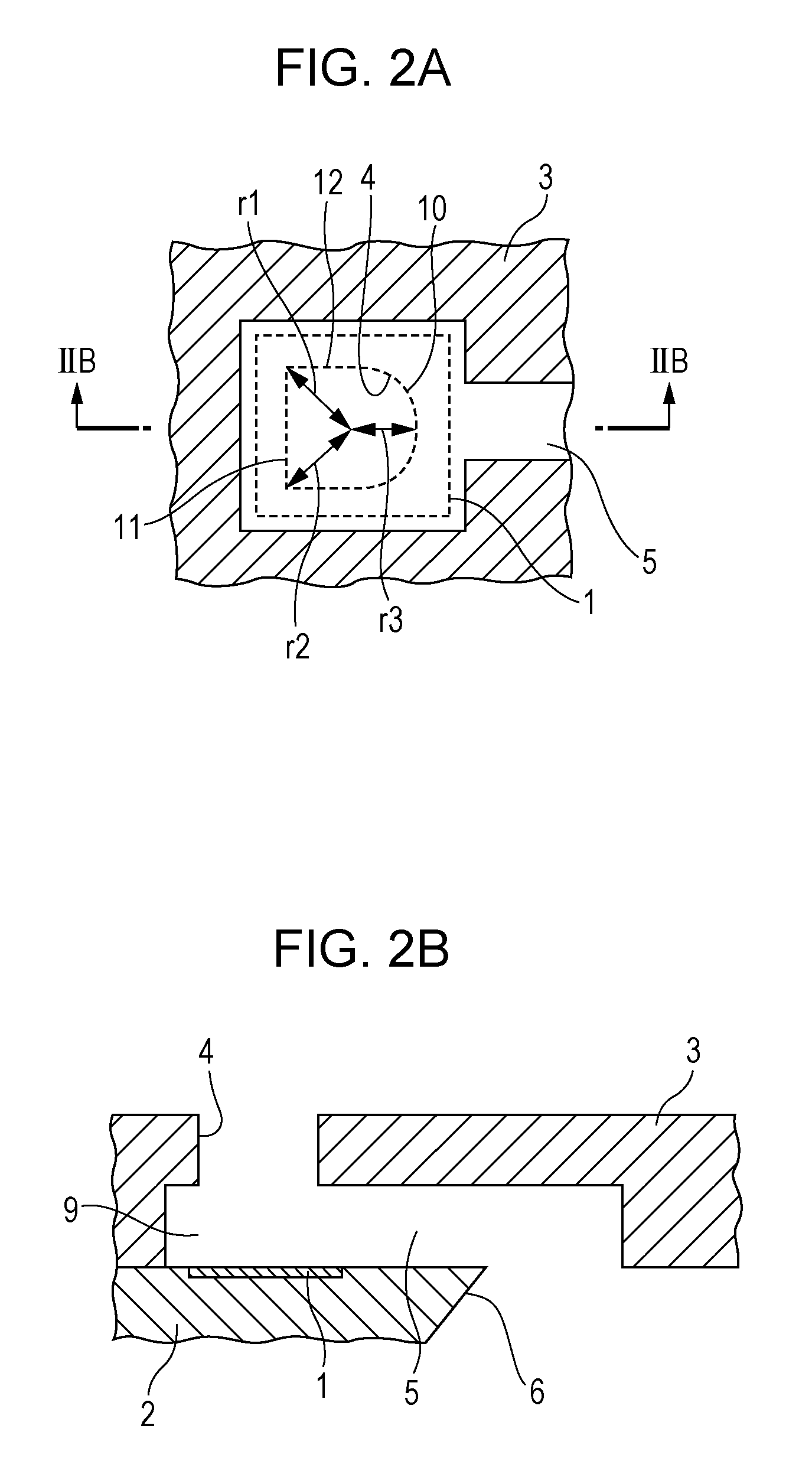
[0039]FIGS. 7A and 7B are a plan view and a cross-sectional view illustrating positional relationship of each of the discharging port 4, discharging flow path 23, bubble generating chamber 9, electrothermal conversion elements 1, and supply path 5 in the liquid discharging head, according to the second embodiment.
[0040]The flow path forming substrate 3 includes the discharging port 4 configured to discharge ink, the bubble generating chamber 9 including the electrothermal conversion element 1, a discharging flow path 23 provided between the discharging port 4 and the bubble ge...
PUM
 Abstract
Description
Claims
Application Information