
Circuit board transportation device, circuit board working apparatus, and conveyor belt

a technology of working apparatus and circuit board, which is applied in the direction of transportation and packaging, electrical components, electric apparatus, etc., can solve the problems of reducing the cross-sectional area of the conveyor belt, difficult to secure sufficient belt strength, and thin circuit board entering such a gap, and achieve excellent stability and versatility. , the effect of stably transporting

Active Publication Date: 2015-09-15
YAMAHA MOTOR CO LTD
View PDF15 Cites 1 Cited by
  • Summary
  • Abstract
  • Description
  • Claims
  • Application Information

AI Technical Summary

Benefits of technology

[0011]An object of the present invention is to provide a circuit board transportation device of excellent stability and versatility capable of stably transporting various types of circuit boards, a circuit board working apparatus equipped with such a circuit board transportation device, and a conveyor belt applied to the circuit board transportation device.

Problems solved by technology

Although these types of circuit board transportation modes have conventionally been developed, applicability thereof to circuit board working apparatuses is limited, leading to a problem with versatility.
When a circuit board to be transported is relatively thin (“thin circuit board”), the thin circuit board enters such a gap and becomes stuck therein.
This situation reduces the cross-sectional area of the conveyor belt, making it difficult to secure sufficient belt strength.
Consequently, transporting a relatively heavy circuit board stretches the conveyor belt, making it difficult to transport the circuit board correctly.
This also might cause breakage of the belt.
For these reasons, prior art 2 can only transport relatively light circuit boards.
Such repeated application of the lateral load to each guide portion repeatedly applies shear force to the part or so-called joint where the guide portion and the transporting unit are connected to each other, leading to problems such as cracking of the joint of the guide portion and breakage of the guide portion.
As a result, the circuit board cannot be transported stably.

Method used


Image

  • Circuit board transportation device, circuit board working apparatus, and conveyor belt
  • Circuit board transportation device, circuit board working apparatus, and conveyor belt
  • Circuit board transportation device, circuit board working apparatus, and conveyor belt

Examples


Embodiment Construction

[0019]An embodiment of the present invention is described hereinafter in detail with reference to the drawings.

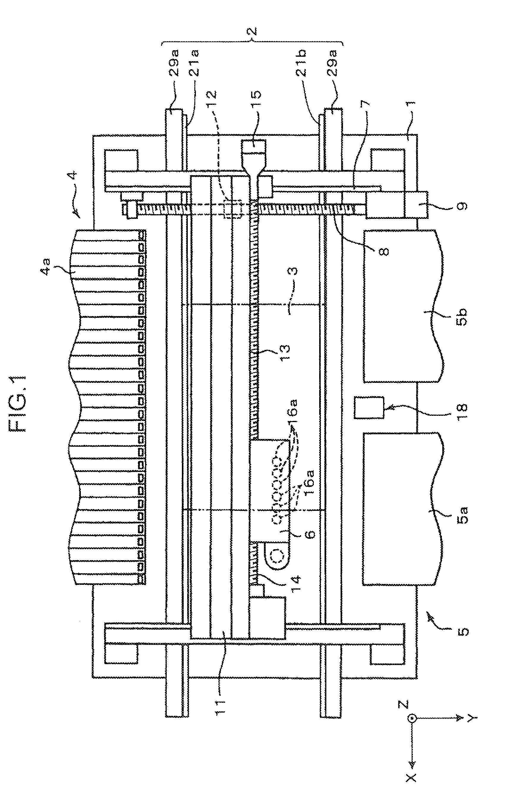
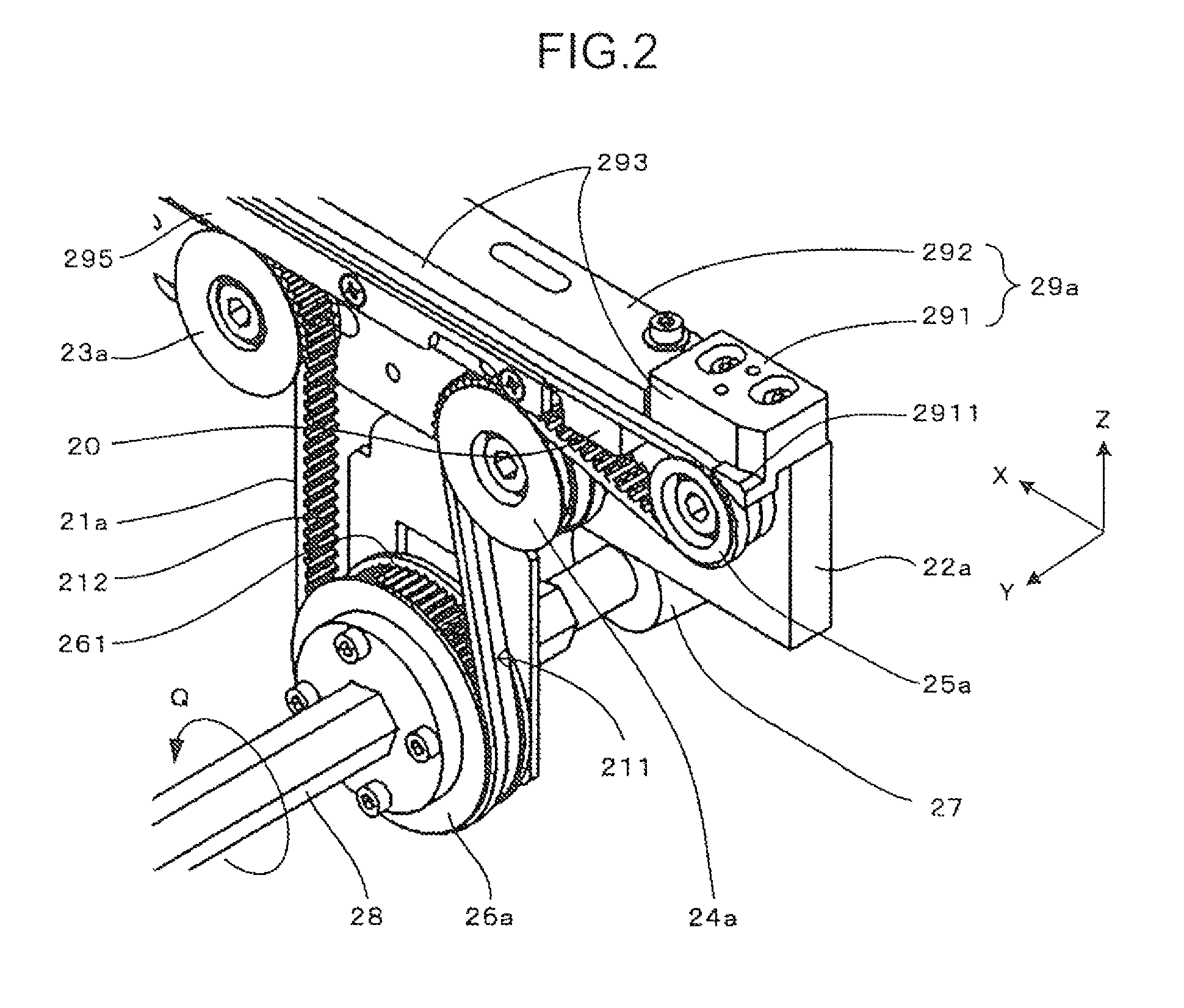
[0020]FIG. 1 is a plan view schematically showing a circuit board working apparatus equipped with a circuit board transportation device according to an embodiment of the present invention. A surface mounter is illustrated as the circuit board working apparatus. For the convenience of description below, FIG. 1 and subsequent diagrams described hereinafter show an XYZ orthogonal coordinate system in which the direction of transporting a circuit board in the circuit board transportation device is illustrated as “X direction,” a vertical direction as “Z direction,” and a direction perpendicular to the X direction (transport direction X) and the Z direction as “Y direction.” In this embodiment, the Y direction corresponds to a perpendicular direction of the present invention.

[0021]The surface mounter has a base 1, as shown in FIG. 1. A circuit board transporting unit 2 correspon...


PUM


Abstract

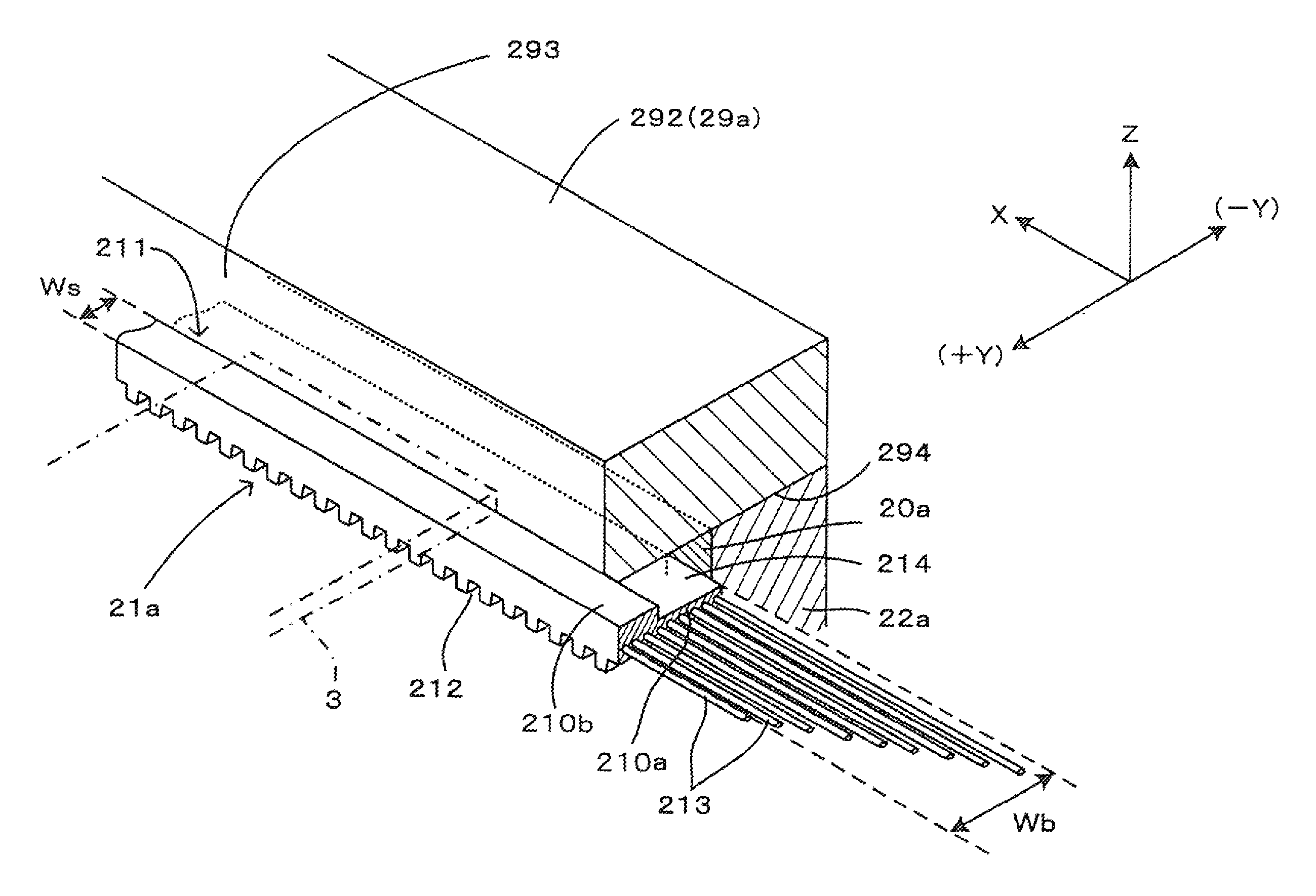
The circuit board transportation device has: a guide member that is provided in such a manner as to extend in the transport direction and has a guide surface that comes into abutment with a circuit board from the outside of the circuit board in a perpendicular direction that is a direction perpendicular to the transport direction; a conveyor belt that extends in the transport direction to support an end of the circuit board; and a drive unit that moves the conveyor belt. The conveyor belt has: a belt base portion that is located under the guide member and extends both ways of the perpendicular direction from the position of the guide surface; and a projection that extends upward from the belt base portion up to a position between upper and lower ends of the guide surface. The conveyor belt supports the circuit board by means of the projection.

Description

BACKGROUND OF THE INVENTION[0001]1. Field of the Invention[0002]The present invention relates to a circuit board transportation device for transporting a circuit board, a circuit board working apparatus for executing a predetermined operation on a circuit board transported to an operation position by a circuit board transportation device, and a conveyor belt suitable for a circuit board transportation device. Examples of the operation carried out by the circuit board working apparatus include surface mounting, circuit board inspection, application of coating, printing, and reflow of a circuit board mounted with parts.[0003]2. Background Art[0004]In a circuit board working apparatus such as a surface mounter, a circuit board is carried into an operation position and then carried out of the operation position upon completion of an operation executed thereon. For the purpose of transporting a circuit board in this manner, the circuit board working apparatus is equipped with a circuit b...

Claims


Application Information

Patent Timeline
Patent Type & Authority Patents(United States)
IPC IPC(8): B65G15/00B65G15/30H05K13/00B65G15/46
CPCB65G15/00B65G15/30H05K13/0061B65G15/46H05K13/02
Inventor OGISO, TAKESHI
Owner YAMAHA MOTOR CO LTD
Learn More