

Nuclear locomotive
Inactive Publication Date: 2009-11-19
TAYLOR WILLIAM GREGORY
View PDF7 Cites 21 Cited by
- Summary
- Abstract
- Description
- Claims
- Application Information
AI Technical Summary
Benefits of technology
[0007]The current application would provide for a considerably wider vehicle that is in current use, perhaps in the range of ten meters. The wider vehicle would provide appropriate space for the nuclear reactors, turbines and condensers; as well as greater stability and versatility for large cargo.
Problems solved by technology
In the current art, the speed and lift capacity of the vehicle are determined by the power supplied from diesel powered electrical generators, which, in turn, limits the field strength of the electromagnets.
Method used
View moreImage
Smart ImageViewing Examples

Examples
Embodiment Construction
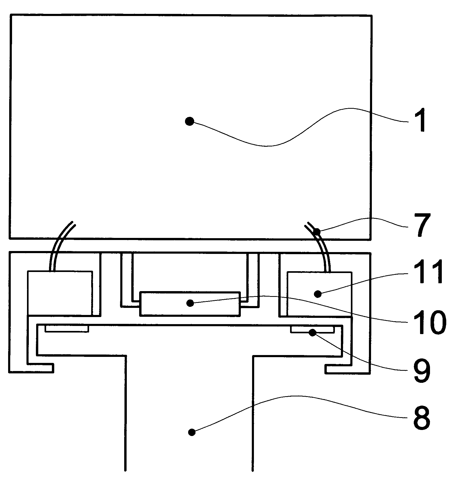
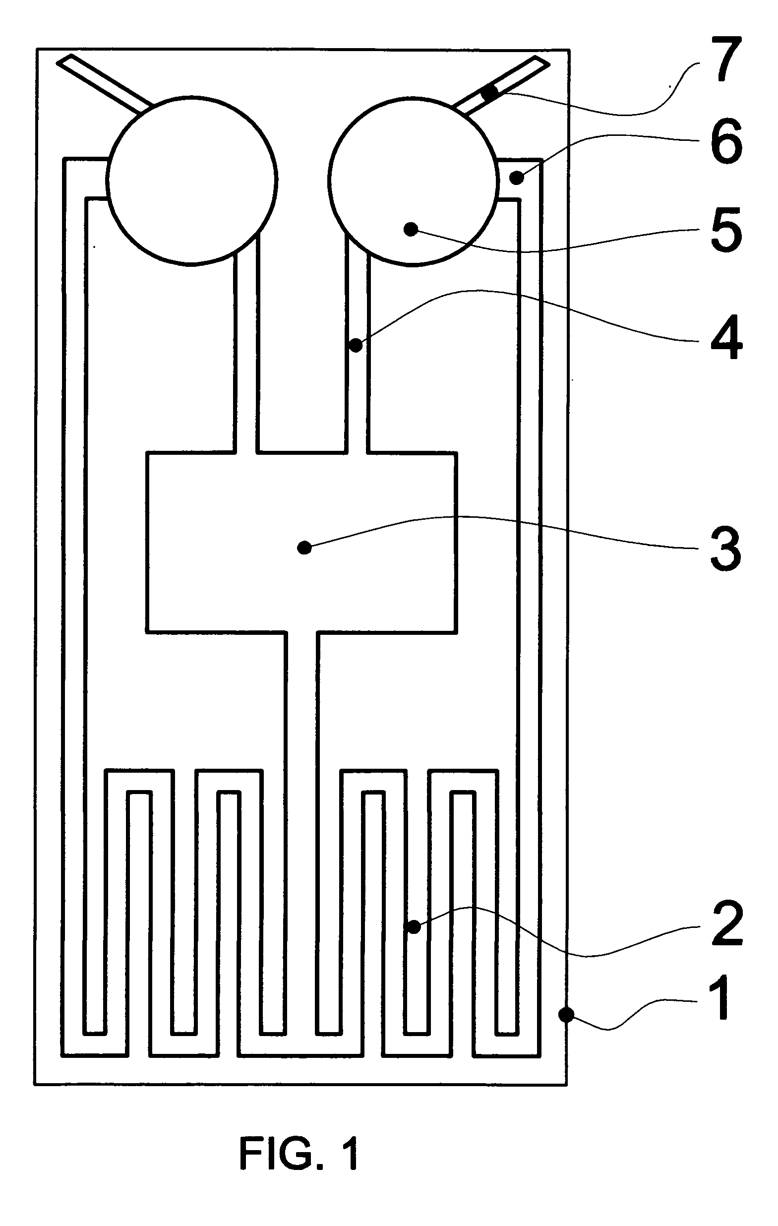
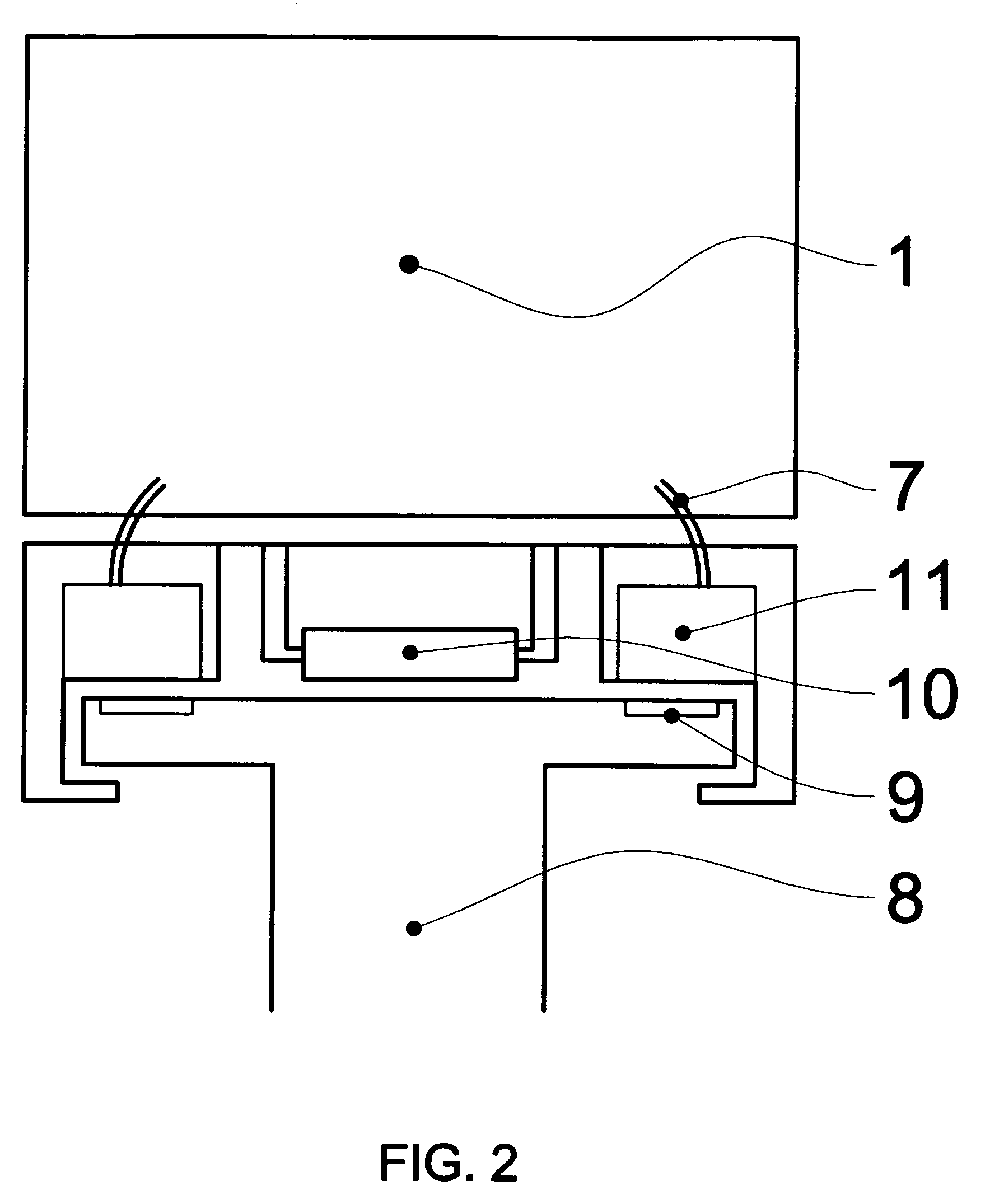
[0012]The object of this invention is a vehicle that travels along a specifically designed roadbed. This vehicle is propelled, levitated, and guided by opposing magnetic forces on the vehicle and in the roadbed. The power source for the superconducting electromagnets is the onboard electrical generator. This generator is run by an onboard nuclear reactor.
[0013]There are numerous configurations for the various elements of the maglev system that have been previously described. The system described here is unique in that it offers greater speed and greater lift capacity due to the incorporation of an onboard nuclear power generator.
Login to View More PUM
 Abstract
This device is a magnetically levitated (maglev) locomotive powered by an onboard nuclear reactor. The locomotive carries a small portable nuclear reactor that heats a fluid to boiling, and passes it through electric turbine engines to produce electric power. The fluid / steam then recirculates through cooling radiators condensing it back to liquid before it passes back into the reactors again. The electric power is used to power and cool the onboard electromagnets, which oppose passive permanent magnets or magnetic coils in the roadbed. The onboard reactor is capable of providing greater electrical power than previously described maglev systems. This, in turn, provides greater power to the superconducting electromagnets, which translates into greater lift capacity and greater speed.
Description
REFERENCES CITED[0001]U.S. PATENT DOCUMENTS7,134,396November 2006Ramu6,250,230June 2001Post6,044,770April 2000Davey5,722,326March 1998Post5,253,592October 1993Coffey5,222,437June 1993Shibata5,085,149February 1992Huson4,913,059April 1990Fujie4,779,538October 1988Fujiwara4,299,173November 1981Arima3,225,228December 1965RoshalaFIELD OF THE INVENTION[0002]The device relates to a specific method of land based vehicle propulsion.DESCRIPTION OF PRIOR ART[0003]The current state of the art for land travel uses electric powered maglev trains. These trains are Levitated, propelled, and guided by setting superconducting electromagnets in opposition to magnetic elements in the roadbed. There are a large number of proposals for the ideal configuration of magnetic elements in the system. Most of these systems employ onboard superconducting electromagnets opposing various configurations of roadway stators to achieve levitation, propulsion and guidance of the vehicle.[0004]The weight levitated and t...
Claims
Login to View More Application Information
Patent Timeline
 IPC IPC(8): B60L11/00B60L13/04B60B19/00
CPCB60L2200/26B60L13/04
InventorTAYLOR, WILLIAM GREGORY
OwnerTAYLOR WILLIAM GREGORY