
Systems and methods for harmonic resonance control

a harmonic resonance and control system technology, applied in the direction of electric variable regulation, process and machine control, instruments, etc., can solve the problems of high complexity and high cost of systems to implement improved effective voltage control, limited switching speed and life of electromechanical switches, etc., to reduce semiconductor device conduction losses, reduce switching stress on relays, and prevent infighting

Active Publication Date: 2015-09-15
SENTIENT ENERGY TECH LLC
View PDF19 Cites 2 Cited by
  • Summary
  • Abstract
  • Description
  • Claims
  • Application Information

AI Technical Summary

Benefits of technology

The patent describes a system that controls the delay of multiple voltage compensators to prevent conflicts and reduce stress on components. The system uses semiconductor switches and relays to control the voltage compensators and reduce conduction losses. Different delays are applied to different members of the system to prevent infIGHTing between them. The technical effect of the invention is to improve the reliability and efficiency of voltage compensation systems.

Problems solved by technology

In recent years, highly complex and expensive systems have been required to implement improved effective voltage control and conservation voltage reduction (CVR) based demand reduction.
The difficulty in adhering to a tight regulation band arises from normal fluctuations in incoming line voltage at the substation, as well as load changes along the feeder.
The electromechanical switches are limited in switching speed and by life of the switches.

Method used


Image

  • Systems and methods for harmonic resonance control
  • Systems and methods for harmonic resonance control
  • Systems and methods for harmonic resonance control

Examples


Embodiment Construction

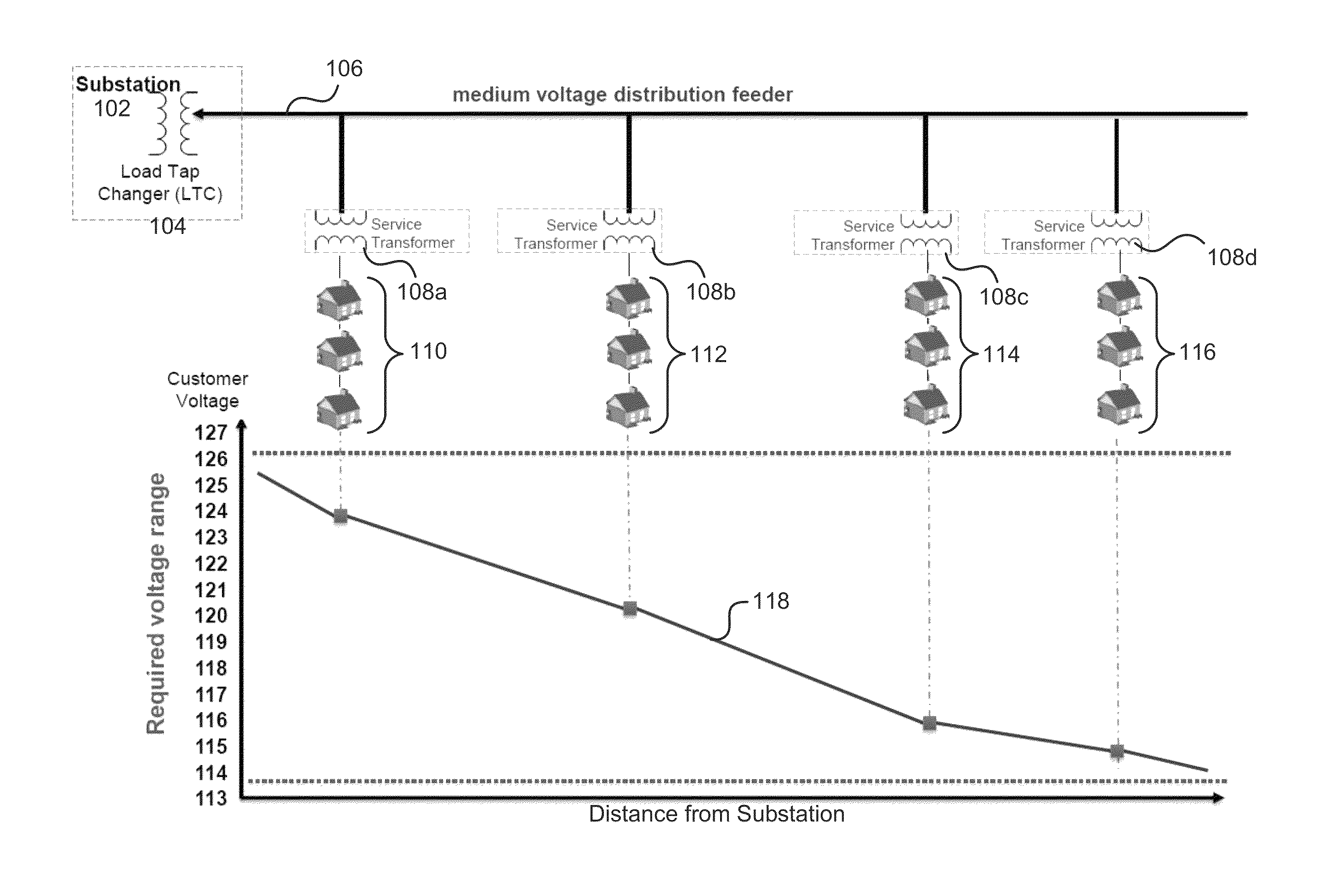
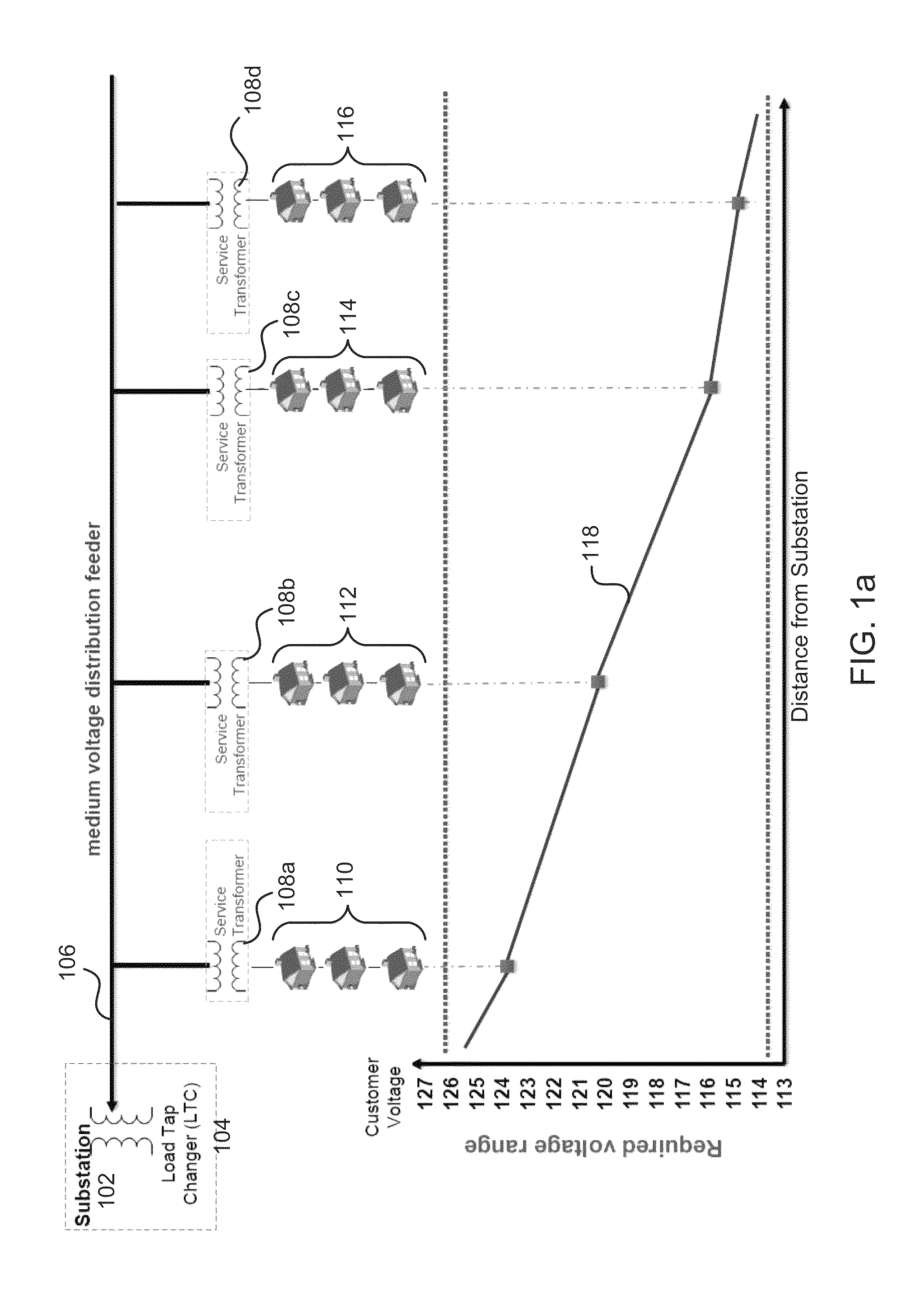
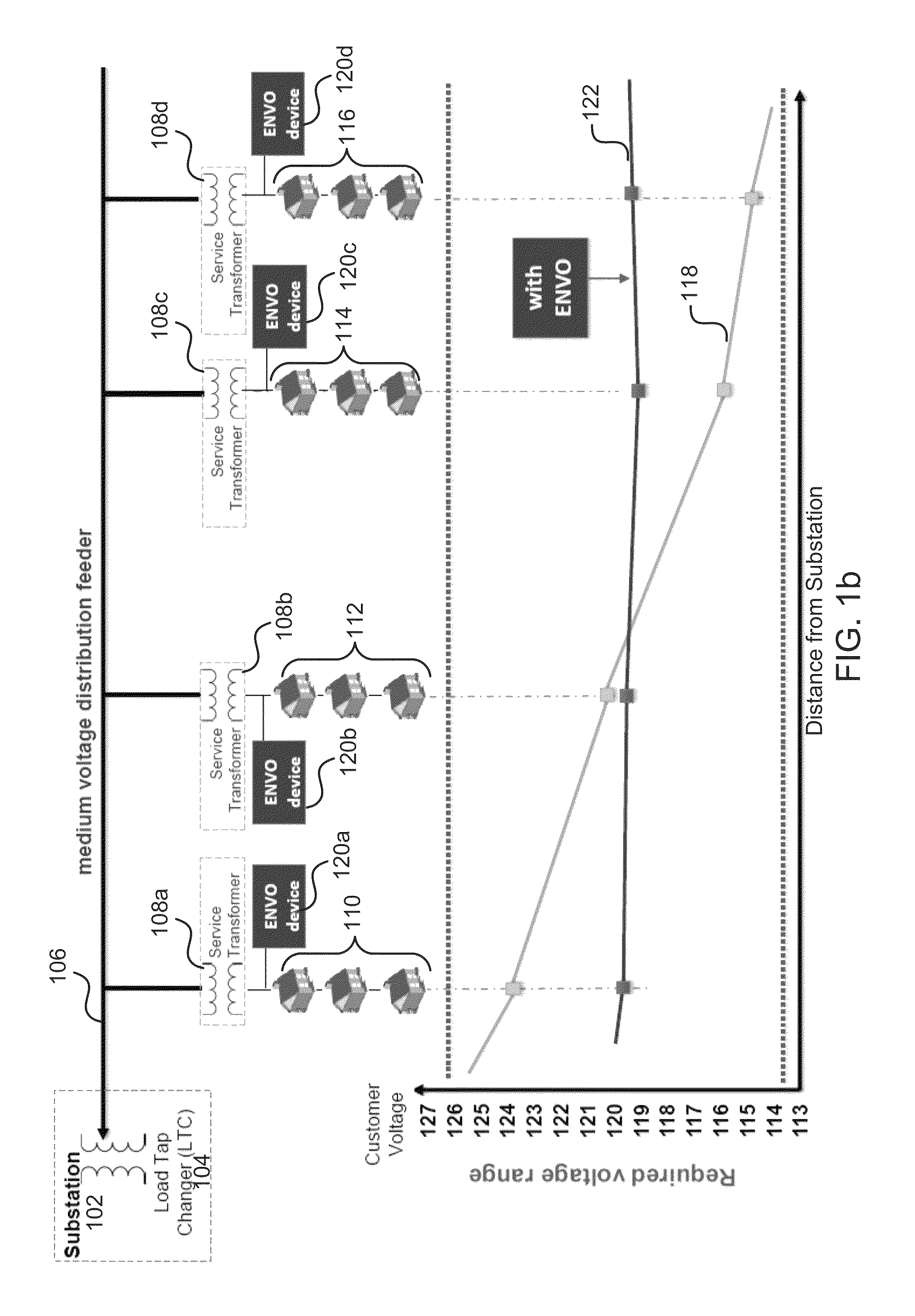
[0085]New requirements for distribution dynamic voltage control are emerging, driven by distribution renewable energy penetration and the need to increase grid capacity without building new lines or infrastructure. Applications such as Conservation Voltage Reduction (CVR) and Volt VAR Optimization (VVO) promise 3-5% increase in system capacity, simply by lowering and flattening the voltage profile along a distribution grid. To achieve CVR and VVO in the prior art, improvements to the power grid are slow in operation, difficult to model due to increased complexity of the overall system, require considerable back end infrastructure (e.g., modeling, and a centralized, computation and communication facility), are expensive to install in sufficient numbers to improve performance, and difficult to maintain. Further, conventional VVO schemes realize poor voltage regulation due to few control elements and poor granular response.

[0086]In various embodiments discussed herein, line voltage may...


PUM


Abstract

Systems and methods for harmonic resonance control are described. In some embodiments, a system comprises a first switch-controlled VAR source and a harmonic management block which may each be configured to be coupled to a distribution power network. The first switch-controlled VAR source may comprise a first processor, a voltage compensation component, and a switch. The first processor may be configured to enable the voltage compensation component after a delay by controlling the switch based on first proximate voltage after a duration associated with the delay to adjust voltage volt-ampere reactive. The harmonic management block may be configured to compare a second proximate voltage to at least one resonant threshold to detect potential resonance caused by enablement of the voltage compensation component and to engage based on the comparison the resonance compensation component to manage the potential resonance.

Description

CROSS-REFERENCE TO RELATED APPLICATIONS[0001]The present application is a continuation-in-part of and claims the benefit of U.S. Nonprovisional patent application Ser. No. 13 / 488,330, filed Jun. 4, 2012, entitled “Systems and Methods for Edge of Network Voltage Control of a Power Grid,” which claims priority to U.S. Provisional Patent Application No. 61 / 535,892, filed Sep. 16, 2011, entitled “Systems and Methods of a Distributed Dynamic VAR (D-DVAR) Compensator,” U.S. Provisional Patent Application No. 61 / 567,580, filed Dec. 6, 2011, entitled “Systems and Methods for Dynamic VAR Optimization,” U.S. Provisional Patent Application No. 61 / 579,610, filed Dec. 22, 2011, entitled “Systems and Methods for Managing Power,” U.S. Provisional Patent Application No. 61 / 635,799, filed Apr. 19, 2012, entitled “Systems and Methods for Dynamic AC Line Voltage Regulation with Energy Saving Tracking,” and U.S. Provisional Patent Application No. 61 / 635,797, filed Apr. 19, 2012, entitled “Systems and M...

Claims


Application Information

Patent Timeline
Patent Type & Authority Patents(United States)
IPC IPC(8): G05F5/00H02J3/18H02J1/10
CPCG05F5/00H02J3/1864H02J3/1878Y02E40/12Y02E40/30Y02E40/10
Inventor DIVAN, DEEPAKRAJ M.PRASAI, ANISH
Owner SENTIENT ENERGY TECH LLC
Learn More