
Rechargeable battery having desirable safety performance

a rechargeable battery and safety performance technology, applied in the field of rechargeable batteries, can solve the problems of high-energy rechargeable batteries producing a lot of gas and a sharp rise in temperature, the security risk of the battery itself, and the inability to release the energy accumulated in the rechargeable battery accident itself, etc., to achieve the effect of desirable safety performan

Active Publication Date: 2015-09-22
DONGGUAN POWERAMP TECH LTD
View PDF0 Cites 1 Cited by
  • Summary
  • Abstract
  • Description
  • Claims
  • Application Information

AI Technical Summary

Benefits of technology

The present invention provides a rechargeable battery with desirable safety performance. The battery includes a battery case and a battery cap, which is connected to the battery case. The battery cap has a conductive cap plate and a second electrode. In normal condition, the second electrode does not contact with the conductive plate. However, when the battery is subject to high pressure, the turnover component of the battery cap can deform and short-circuit the first and second electrodes, releasing the internal energy of the battery and ensuring safety performance. The rechargeable battery has a snap joint portion that engages with a groove to establish a planar contact, ensuring the safety of the battery.

Problems solved by technology

When accident occurs due to improper charging, short circuit or exposure to high temperature, high-energy rechargeable battery will produce a lot of gas and a sharp rise in temperature.
The high pressure gas opens the pressure relief valve to achieve the purpose of pressure relief Although the arrangement of the pressure relief valve can improve the safety performance of a rechargeable battery, the energy accumulated in a rechargeable battery with accident itself cannot be released.
Therefore, the battery itself is a security risk.
If the battery is continued to be overcharged after accidents, it will lead to serious safety accidents.

Method used


Image

  • Rechargeable battery having desirable safety performance
  • Rechargeable battery having desirable safety performance
  • Rechargeable battery having desirable safety performance

Examples


Embodiment Construction

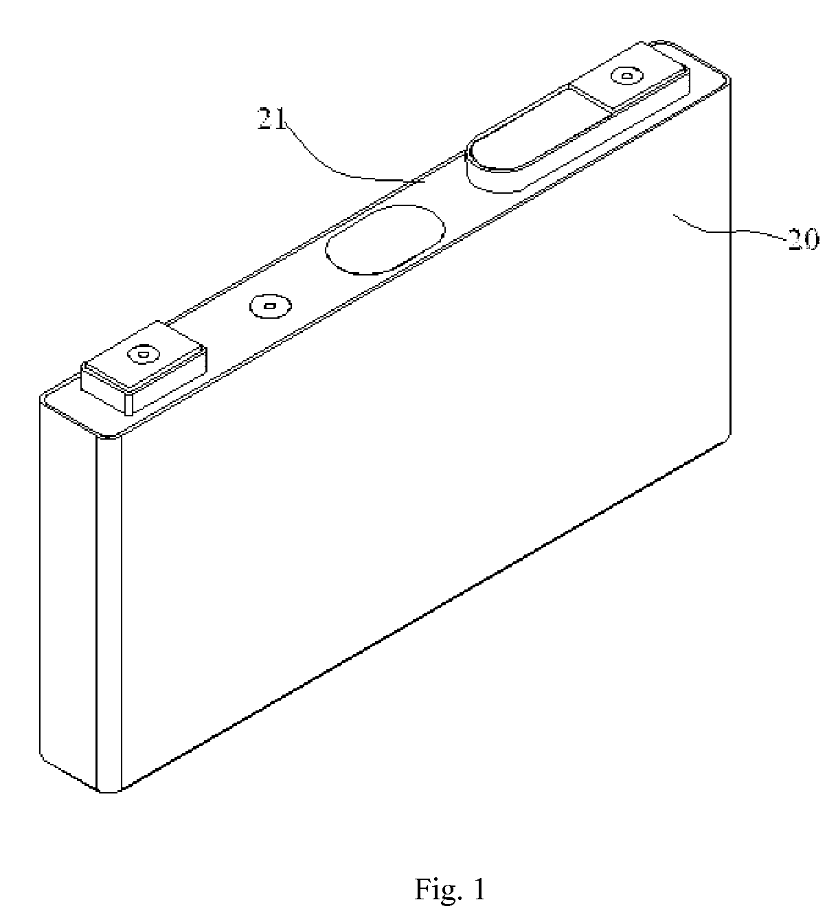
[0030]Referring to FIG. 1, a rechargeable battery according to one embodiment of the present invention includes a battery case 20 and a battery cap 21 provided on the battery case 20 for sealing the battery case 20.

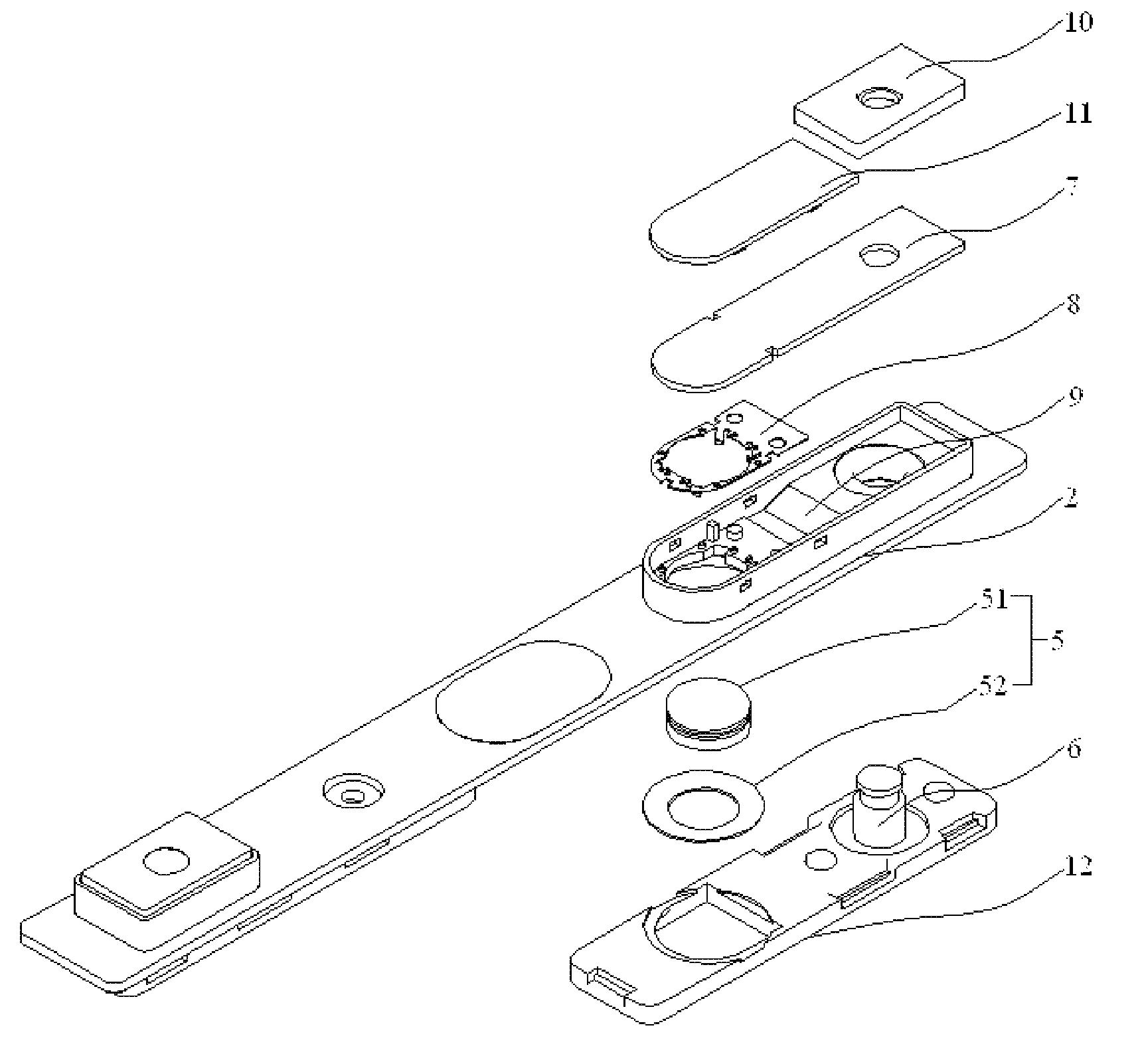
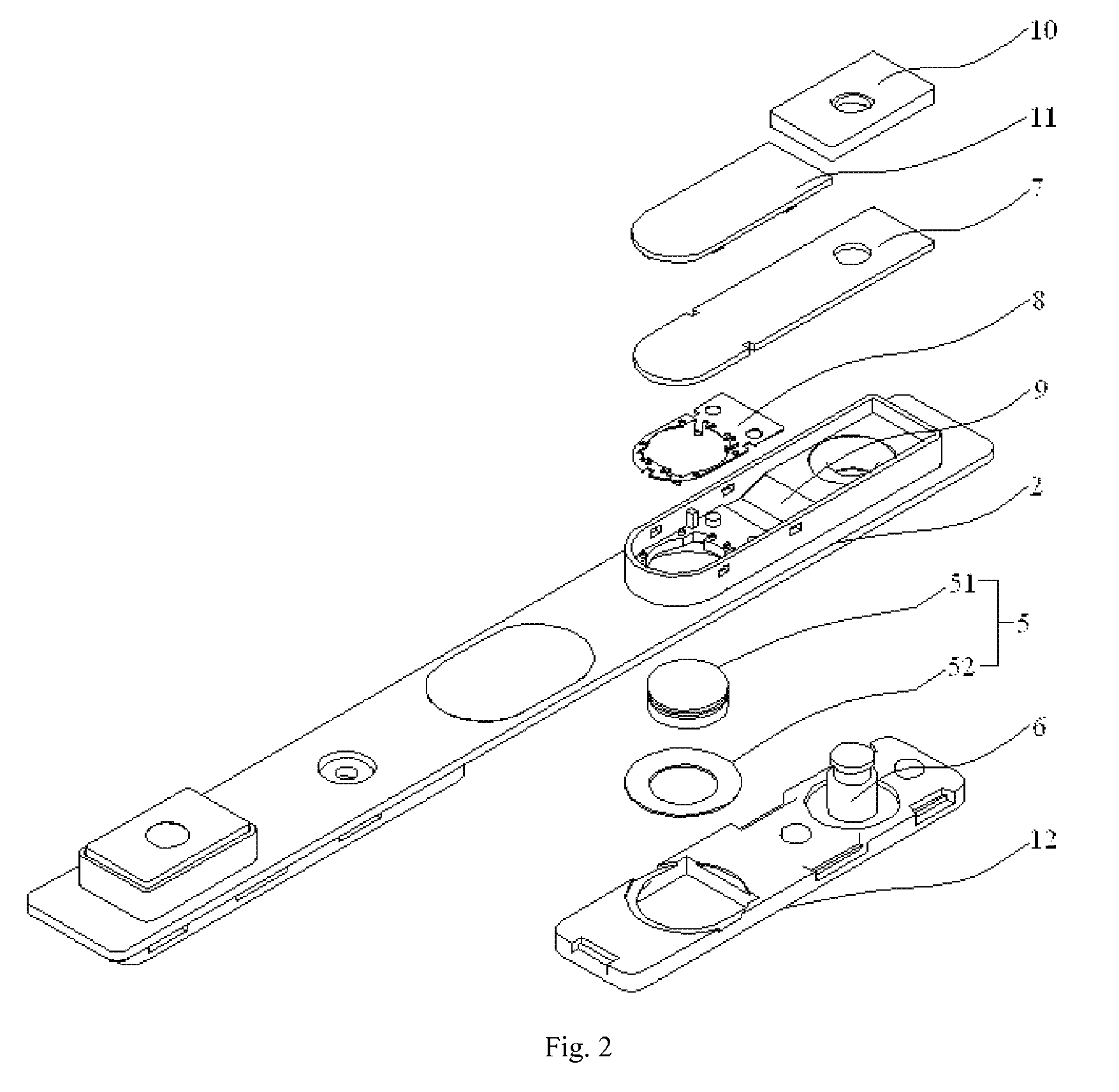
[0031]Referring to FIG. 2 to FIG. 6, the battery cap 21 includes a conductive cap plate 2 defining an electrolyte injection hole 3 and formed with a pressure relief valve 4, a first electrode 1 electrically connected to the cap plate 2, a second electrode 6 coupled to the cap plate 2 insulatively and in electrical connection with one end of a conductive plate 7 for securing the second electrode 6 to the cap plate 2, and a conductive turnover component 5 in electrical connection with the cap plate 2. The turnover component 5 is initially separated from the conductive plate 7 and capable deforming to contact the other end of the conductive plate 7 due to high pressure in the battery case 20, to short-circuit the first electrode 1 and the second electrode 6.

[0032]The first e...


PUM

PropertyMeasurementUnit
pressureaaaaaaaaaa
pressureaaaaaaaaaa
conductiveaaaaaaaaaa

Abstract

The present application provides a rechargeable battery including a battery case and a battery cap coupled to the battery case. The battery cap includes a conductive cap plate; a first electrode electrically connected to the cap plate; a second electrode insulatively connected to the cap plate, the second electrode being in electrical connection with one end of a conductive plate for securing the second electrode to the conductive cap plate; and a conductive turnover component in electrical connection with the conductive cap plate, the turnover component being initially separated from the conductive plate and capable deforming to contact other end of the conductive plate due to high pressure in the battery case, so as to short-circuit the first electrode and the second electrode.

Description

CROSS-REFERENCE TO RELATED APPLICATION[0001]The present patent application claims priority to Chinese Patent Application No. CN 201320028704.0 filed Jan. 21, 2013, which is incorporated by reference herein in its entirety.FIELD OF THE INVENTION[0002]The present invention generally relates to rechargeable batteries and, more particularly, relates to a rechargeable battery which has desirable safety performance.BACKGROUND OF THE INVENTION[0003]With rapid development of technology and people's awareness of environmental protection, rechargeable batteries are becoming increasingly popular as power sources in various devices, for instance, mobile phones, laptop computers, power tools and electric automobiles.[0004]Electric automobiles and energy storage power stations generally need high capacity rechargeable batteries as power sources. In addition to high capacity, generally, a rechargeable battery should also have excellent safety performance and long cycle service life, so as to meet ...

Claims


Application Information

Patent Timeline
Patent Type & Authority Patents(United States)
IPC IPC(8): H01M2/34
CPCH01M2/345H01M2200/20Y02E60/10H01M50/578
Inventor CAI, RU LAILI, QUAN KUNDENG, PING HUAWANG, PENG
Owner DONGGUAN POWERAMP TECH LTD
Learn More