
Plasma etching method and plasma processing apparatus

a technology of plasma processing apparatus and etching method, which is applied in the direction of electrical apparatus, basic electric elements, electric discharge tubes, etc., can solve the problems of difficult to make the line width of the etching target film a desired value, and difficulty in precisely adjusting the size in the horizontal direction of the etching mask

Active Publication Date: 2015-09-29
TOKYO ELECTRON LTD
View PDF6 Cites 0 Cited by
  • Summary
  • Abstract
  • Description
  • Claims
  • Application Information

AI Technical Summary

Benefits of technology

[0009]In view of the above, the present invention provides a plasma etching method of performing a plasma etching process by using a EUV resist as a mask, which is capable of performing micro-fabrication with a desired dimensional precision on an etching-target film by improving the remaining of the EUV resist mask after etching.
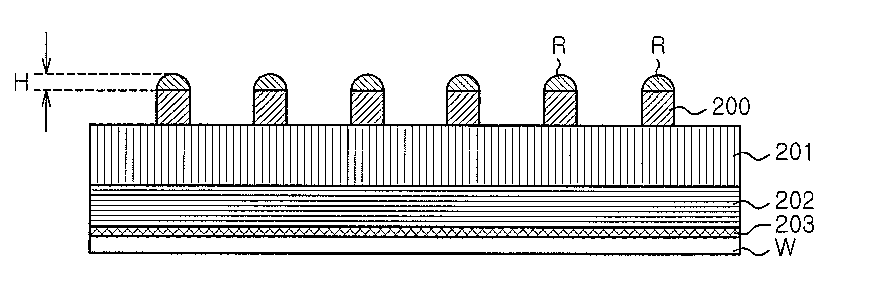
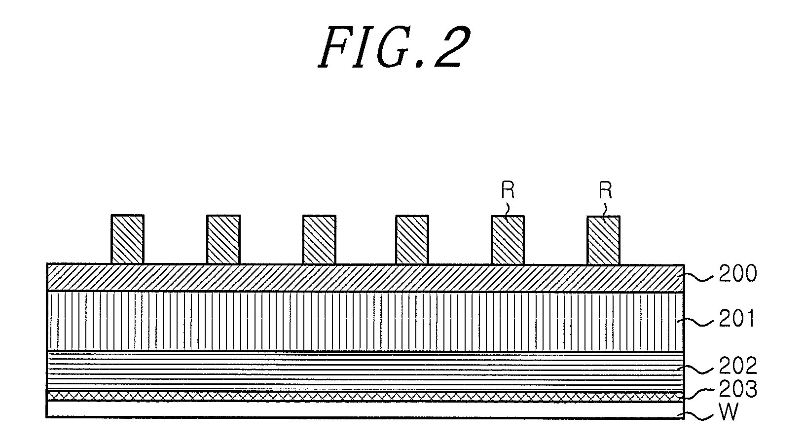
[0011]According to tests performed by the present inventors, it has been confirmed that the Si-containing compound was deposited more thickly on the upper surface of the resist film than on the side surface thereof by pre-coating the resist film with a gas containing SiCl4 or SiF4 supplied into the processing chamber. The present invention is based on the tests and, according to the present invention, the Si-containing compound is deposited on the resist film by using the gas containing SiCl4, before etching. At this time, the Si-containing compound is deposited more thickly on the upper surface of the resist film than on the side surface thereof. Accordingly, a thickness of the remaining resist film after the plasma etching process can be prevented from becoming below a desired thickness. As a result, even when an etching mask having a small thickness such as, e.g., EUV resist is used, a masked portion of the antireflection film can be prevented from being etched in the height direction thereof. Further, since an increase in a width direction of the resist film is suppressed to a minimum due to the pre-coating, an effect on a line width of the antireflection film after etching can be suppressed to a minimum. Therefore, according to the present invention, the micro-fabrication can be performed with a desired dimensional precision on the etching-target film.
[0020]In accordance with the present invention, in performing the plasma etching process by using a EUV resist as the mask, micro-fabrication can be performed with a desired dimensional precision on an etching-target film by improving the remaining portions of the EUV resist mask after etching.

Problems solved by technology

However, as disclosed in the above-cited reference, when the etching mask is formed by the anisotropic etching, it is very difficult to precisely adjust a size in the horizontal direction of the etching mask.
Therefore, it is difficult to make the line width of the etching-target film be a desired value.

Method used


Image

  • Plasma etching method and plasma processing apparatus
  • Plasma etching method and plasma processing apparatus
  • Plasma etching method and plasma processing apparatus

Examples


Embodiment Construction

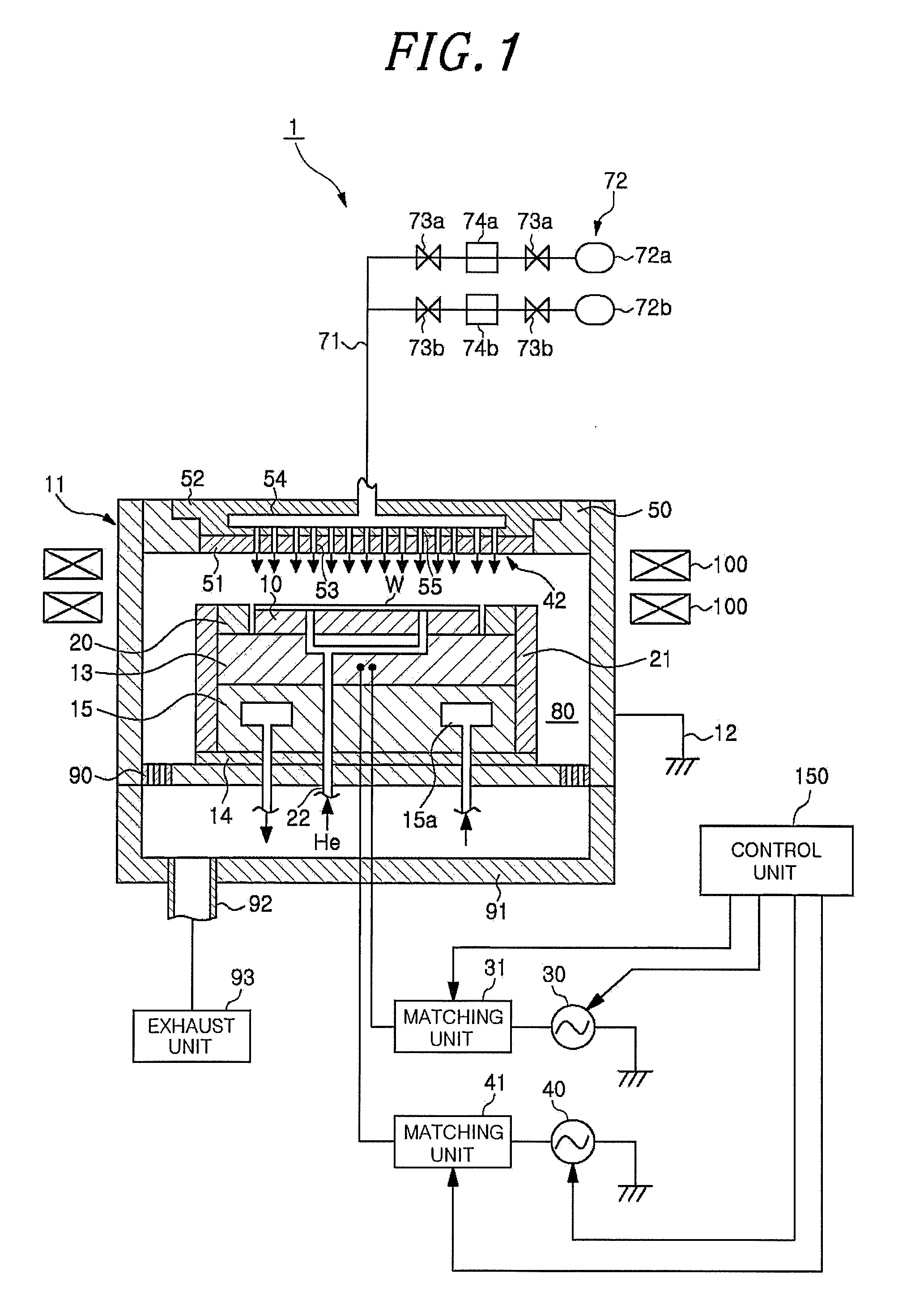
[0029]Hereinafter, embodiments of the present invention will be described with reference to the accompanying drawings which form a part hereof. FIG. 1 is a vertical sectional view showing a schematic configuration of a plasma processing apparatus 1 in accordance with an embodiment of the present invention.

[0030]The plasma processing apparatus 1 includes a substantially cylindrical processing chamber 11 provided with a wafer chuck 10 for supporting a wafer W that is a silicon substrate. The processing chamber 11 is electrically grounded by a ground wire. The inner wall of the processing chamber 11 is covered with a liner (not shown) of which surface is covered with a thermal spray coating made of a plasma resistant material.

[0031]The bottom surface of the wafer chuck 10 is supported by a susceptor 13 serving as a lower electrode. The susceptor 13 is substantially disc-shaped and made of a metal such as, e.g., aluminum. On the bottom portion of the processing chamber 11, there is prov...


PUM

PropertyMeasurementUnit
thicknessaaaaaaaaaa
thicknessaaaaaaaaaa
frequencyaaaaaaaaaa

Abstract

A plasma etching method for plasma etching, in a processing chamber, an antireflection film laminated on an organic film formed on a substrate by using an etching mask made of a resist film formed on the antireflection film, the plasma etching method includes: depositing a Si-containing compound on the etching mask made of the resist film by using plasma of Si-containing gas in the processing chamber; and etching the antireflection film in a state where the Si-containing compound is deposited on the etching mask.

Description

CROSS-REFERENCE TO RELATED APPLICATIONS[0001]This application claims priorities to Japanese Patent Application No. 2012-086179 filed on Apr. 5, 2012, and U.S. Provisional Application No. 61 / 623,689 filed on Apr. 13, 2012, the entire contents of each of which are incorporated herein by reference.FIELD OF THE INVENTION[0002]The present invention relates to a method of performing plasma etching on an object to be processed and a plasma processing apparatus for performing the plasma etching.BACKGROUND OF THE INVENTION[0003]Recently, with a trend toward miniaturization and high-integration of semiconductor devices, EUV (Extreme Ultra Violet) lithography technology using EUV light of 13.5 nm, which is shorter compared to an ArF excimer laser (with wavelength of 193 nm) mainly used in current photolithography technologies of semiconductor devices, is drawing attention as a next generation technology that makes it possible to fabricate a hyperfine pattern of 20 nm or less.[0004]However, a t...

Claims


Application Information

Patent Timeline
Patent Type & Authority Patents(United States)
IPC IPC(8): H01L21/3065H01L21/67H01J37/32H01L21/311H01L21/027
CPCH01L21/3065H01J37/32669H01L21/31138H01L21/31144H01L21/67069H01J2237/334H01L21/0276
Inventor KATSUNUMA, TAKAYUKIHONDA, MASANOBUICHIKAWA, HIRONOBUKUDO, JIN
Owner TOKYO ELECTRON LTD
Learn More