Family of cutting inserts, milling cutting tool, and cutting insert

a cutting tool and insert technology, applied in the field of cutting inserts, can solve problems such as creating chatter effects, and achieve the effects of avoiding high feed per tooth, high radial cutting force, and high leading angl

Active Publication Date: 2015-10-06
SECO TOOLS AB
View PDF24 Cites 2 Cited by
  • Summary
  • Abstract
  • Description
  • Claims
  • Application Information

AI Technical Summary

Benefits of technology

[0002]In milling cutting operations, use of an insert of circular shape permits providing a depth of cut equal to one half of insert diameter, or generating a radius at the bottom of a workpiece. The leading angle of a milling cutting tool with a circular insert depends on depth of cut. The higher the depth of cut is, the higher the leading angle is. To reach the maximum material removal rate using circular inserts, the conventional strategy is to machine with high depth and avoid reaching a high feed per tooth. This strategy tends to create high radial cutting forces which are acceptable when the tool overhang is short but which create chatter effects when total tool length becomes large.
[0003]With a high feed insert, such as an insert having four cutting edges, the maximum depth of cut is reduced due to the insert shape and, consequently, the leading angle is reduced. To reach the maximum material removal rate using a high feed insert, the strategy differs from that used with circular inserts. Because the leading angle and depth of cut is typically reduced in a multi-edge insert relative to a circular insert, the feed per tooth can be increased. This strategy tends to reduce radial cutting forces (at least relative to high depth of cut and / or high leading angle operations), which can be a benefit when long overhang is necessary.
[0004]When using a finishing insert, the depth of cut and the leading angle are generally reduced further, and feed rate can be increased further.

Problems solved by technology

This strategy tends to create high radial cutting forces which are acceptable when the tool overhang is short but which create chatter effects when total tool length becomes large.

Method used


Image

  • Family of cutting inserts, milling cutting tool, and cutting insert
  • Family of cutting inserts, milling cutting tool, and cutting insert
  • Family of cutting inserts, milling cutting tool, and cutting insert

Examples


Embodiment Construction

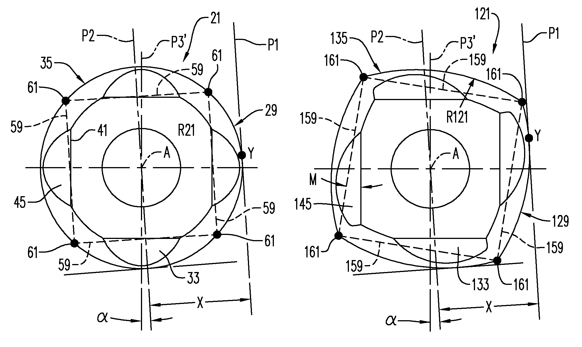
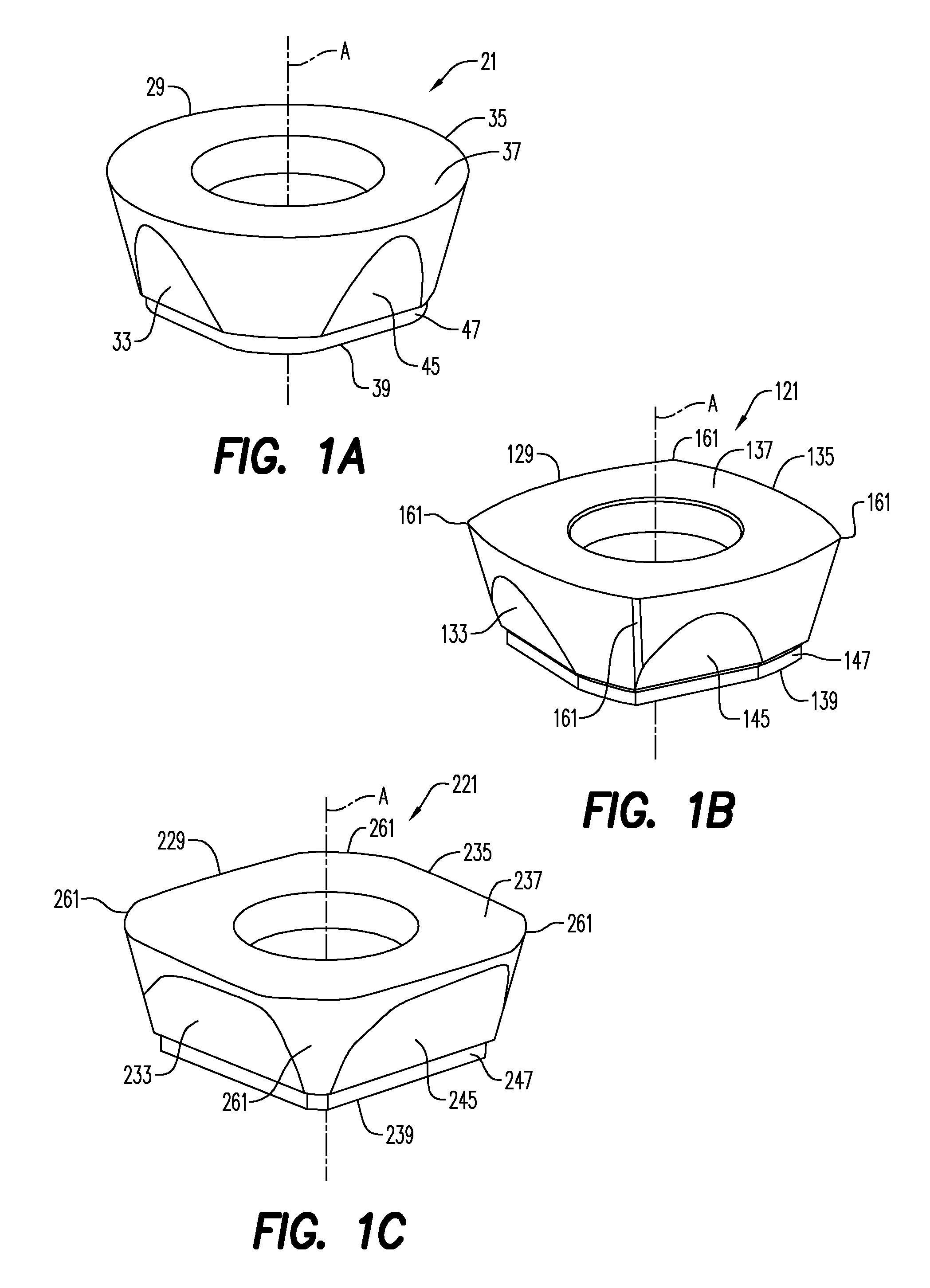
[0021]Different inserts 21, 121, 221 of a family of cutting inserts are shown in FIGS. 1A-1C. Each insert 21, 121, 221 has a different geometry, such as, but not necessarily, having cutting edges that are of different shapes when viewed in plan. For illustrative purposes, the insert 21 has a circular shape when viewed in plan, the insert 121 has a four-sided shape when viewed in plan with cutting edges having radii equal to a diameter of a circle inscribed in the corresponding circular insert 21 and with radiused corners between the cutting edges, and the insert 221 has a four-sided shape when viewed in plan with cutting edges having radii greater than the diameter of a circle inscribed in the insert and with a plurality of (three) chamfers between the cutting edges. The differences in geometry can involve other features of the insert, instead of or in addition to the cutting edges, such as the presence or absence of chipbreakers, flat or curved wiper surfaces, etc.

[0022]Each insert...


PUM

PropertyMeasurementUnit
angleaaaaaaaaaa
angleaaaaaaaaaa
axial angleaaaaaaaaaa

Abstract

A family of cutting inserts includes a plurality of different inserts, each having a different geometry. Each insert of the plurality of different inserts is adapted to be mounted in a common insert-receiving pocket on a toolholder of a milling cutting tool so that an outer diameter generated by the milling cutting tool is the same, regardless which insert of the plurality of inserts is mounted in the pocket.

Description

BACKGROUND AND SUMMARY[0001]The present invention relates generally to cutting inserts and, more particularly, to families of cutting inserts usable in the same toolholders.[0002]In milling cutting operations, use of an insert of circular shape permits providing a depth of cut equal to one half of insert diameter, or generating a radius at the bottom of a workpiece. The leading angle of a milling cutting tool with a circular insert depends on depth of cut. The higher the depth of cut is, the higher the leading angle is. To reach the maximum material removal rate using circular inserts, the conventional strategy is to machine with high depth and avoid reaching a high feed per tooth. This strategy tends to create high radial cutting forces which are acceptable when the tool overhang is short but which create chatter effects when total tool length becomes large.[0003]With a high feed insert, such as an insert having four cutting edges, the maximum depth of cut is reduced due to the ins...

Claims


Application Information

Patent Timeline
Patent Type & Authority Patents(United States)
IPC IPC(8): B23C5/20B23C5/06
CPCB23C5/06B23C5/202B23C5/20B23C2200/045B23C2200/125B23C2200/203B23C2210/168Y10T407/1924Y10T407/20Y10T407/21Y10T407/23
Inventor MICHELET, BENJAMINRIVIERE, BERTRANDJUBLOT, CATHERINEAUZENAT, FRANCOIS
Owner SECO TOOLS AB
Why Eureka
Try Eureka