AI technical title is built by Patsnap AI team. It summarizes the technical point description of the patent document.
a winch and sleeve technology, applied in the field of sleeve, can solve problems such as problems such as problems such as stumbling a rope from the sheave, and achieve the effect of preventing damage or minimizing the damage to the spring
Inactive Publication Date: 2015-10-06
SKYBA HELMUT K
View PDF3 Cites 6 Cited by
Summary
Abstract
Description
Claims
Application Information
AI Technical Summary
This helps you quickly interpret patents by identifying the three key elements:
Problems solved by technology
Method used
Benefits of technology
Benefits of technology
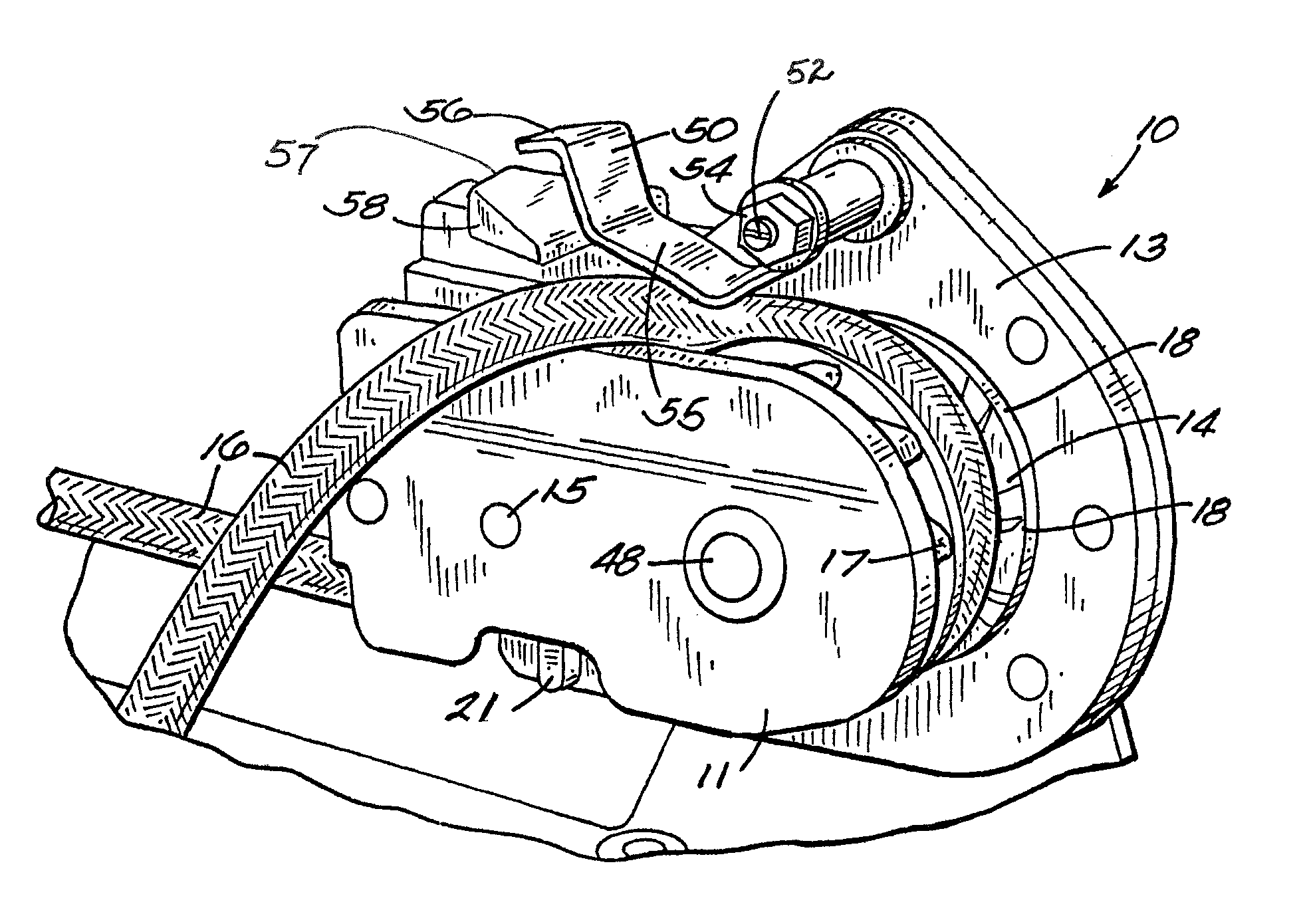
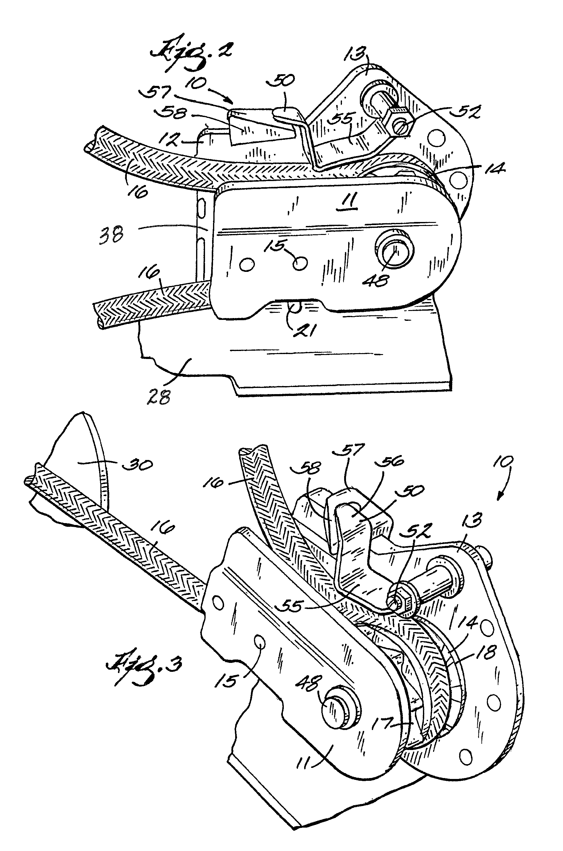
[0006]The improvements provided by this invention relate to a sheave assembly wherein the rope or cable is self-feeding onto the sheave by virtue of a spring located adjacent to the sheave that is biased so as to push a rope into contact with the grooved surface of the sheave. One end of the spring is pivotally supported on the frame that supports the sheave for rotation about its central axis, while the opposite end is freely flexible. In accordance with an additional feature, a supporting block is provided at the free end of the spring to support and minimize or prevent damage to the spring. This feature is preferably in the form of a block for supporting the spring that has an angled surface for urging the rope away from the sheave, thus, together with a stripper member, assisting removal of the rope from the sheave at a selected rotational location, preferably near the point at which the rope exits the sheave.
Problems solved by technology
While my previous devices, referred to above, have proved workable, the feeding of a rope onto the sheave has often proved troublesome in that manual assistance may be necessary, and even stripping a rope from the sheave can be problematic.
Method used
Image
Click on the blue label to locate the original text in one second.
Reading with bidirectional positioning of images and text.
Examples
Embodiment Construction
[0014]Referring more specifically to the drawings, preferred embodiment of winch 10, intended to be tightened by a hand crank 18, is shown in FIG. 1. Device 10 includes a housing 12 formed from divisible halves 11 and 13 which are attached together as seen in FIG. 2 by conventional mechanical fasteners such as threaded bolts 15. Rotatably held within housing 12 is a sheave 14. Sheave 14, for ease of manufacture, is formed from halves 17 and 18. Halves 17 and 18 may be threaded together as shown in my earlier mentioned patents. Alternatively, each half can be threaded onto a threaded shaft 48 as shown.
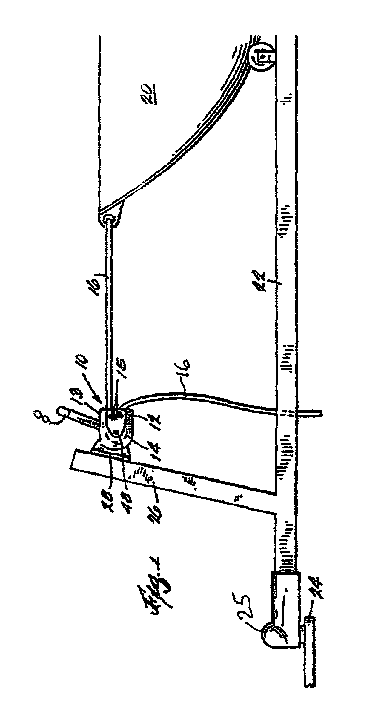
[0015]The winch 10 can be attached to a suitable surface on a trailer 22, for example, a vertical member 26 or alternatively on a horizontal member. In FIG. 1 a bracket 28 is used for that purpose. Boat 20 is loaded on the trailer in conventional fashion and connected to a ball hitch 24 of a towing motor vehicle by means of a clamp member 25 as is also conventional. The inner face of ea...
PUM
Abstract
A winch wherein a rope or cable is self-feeding onto a sheave by a spring that is biased so as to push a rope into contact with a grooved outer surface of the sheave. One end of the spring is pivotally supported on a frame that supports the sheave for rotation about its central axis, while the opposite end of the spring is freely flexible. A supporting block is provided for the free end of the spring to support and minimize or prevent damage to the spring. The block has an angled surface for urging the rope away from the sheave, thus, together with a stripper member, assisting removal of the rope from the sheave at a point at which the rope exits the sheave.
Description
CROSS REFERENCE TO RELATED APPLICATIONS[0001]This application claims priority to U.S. provisional application Ser. No. 61 / 611,290 entitled, “Improved Winch,” filed Mar. 15, 2012.BACKGROUND OF THE INVENTION[0002]This application provides improvements of the devices described and claimed in my earlier applications: Ser. No. 382, filed Jan. 4, 1993, now U.S. Pat. No. 5,368,281 issued Nov. 29, 1994; Ser. No. 719636, filed Sep. 25, 1996, now U.S. Pat. No. 5,722,640 issued Mar. 3, 1998; and Ser. No. 974177 filed Nov. 19, 1997, now U.S. Pat. No. 6,149,133 issued Nov. 21, 2000. The disclosure of said patents is incorporated herein by reference.[0003]The present invention to an improved winch that incorporates a sheave, wherein a rope is pulled under tension by either manual or power-driven rotational forces applied to the sheave. This invention relates to pulleys for tightening and tensioning ropes or cords having a ratchet mechanism to permit retaining the same under tension, and more part...
Claims
Application Information
Patent Timeline
Application Date:The date an application was filed.
Publication Date:The date a patent or application was officially published.
First Publication Date:The earliest publication date of a patent with the same application number.
Issue Date:Publication date of the patent grant document.
PCT Entry Date:The Entry date of PCT National Phase.
Estimated Expiry Date:The statutory expiry date of a patent right according to the Patent Law, and it is the longest term of protection that the patent right can achieve without the termination of the patent right due to other reasons(Term extension factor has been taken into account ).
Invalid Date:Actual expiry date is based on effective date or publication date of legal transaction data of invalid patent.

