Shape discrimination vision assessment and tracking system

a technology of shape discrimination and vision assessment, applied in the field of design and implementation of vision testing and assessment systems, can solve the problems of limited monitoring value, rapid degeneration of diseases, and potential active and active diseases, and achieve the effects of reducing the risk of blindness, permanent vision loss or even blindness

Active Publication Date: 2015-10-13
GENENTECH INC
View PDF33 Cites 15 Cited by
  • Summary
  • Abstract
  • Description
  • Claims
  • Application Information

AI Technical Summary

Benefits of technology

[0008]The foregoing has outlined various features of the invention so that those skilled in the pertinent art may better understand the detailed description of the invention that follows. Additional features of the invention will be described hereinafter that form the subject of the claims of the invention. Those skilled in the pertinent art should appreciate that they can readily use the disclosed conception and specific embodiment as a basis for designing or modifying other structures for carrying out the same purposes of the invention. Those skilled in the pertinent art should also realize that such equivalent constructions do not depart from the scope of the invention.

Problems solved by technology

Use of vision charts is suitable for analysis of common vision problems such as focusing disorders, but they are of limited value for monitoring more serious disorders such as diabetic retinopathy, age-related macular degeneration, and other serious disorders.
These diseases have the potential to become active and degenerate rapidly.
If not properly treated, permanent vision loss or even blindness may occur.
However, they generally require expensive and sophisticated equipment that must be operated by a specially trained technician, such as an optometrist or an ophthalmologist.
While simple and low cost, the Amsler grid is difficult to use since the individual must subjectively assess their own condition, it is not quantitative, and it can be very hard for patients to determine if missing, wavy, or distorted grid segments are slightly more or less pronounced from one test to the next.

Method used


Image

  • Shape discrimination vision assessment and tracking system
  • Shape discrimination vision assessment and tracking system
  • Shape discrimination vision assessment and tracking system

Examples


Embodiment Construction

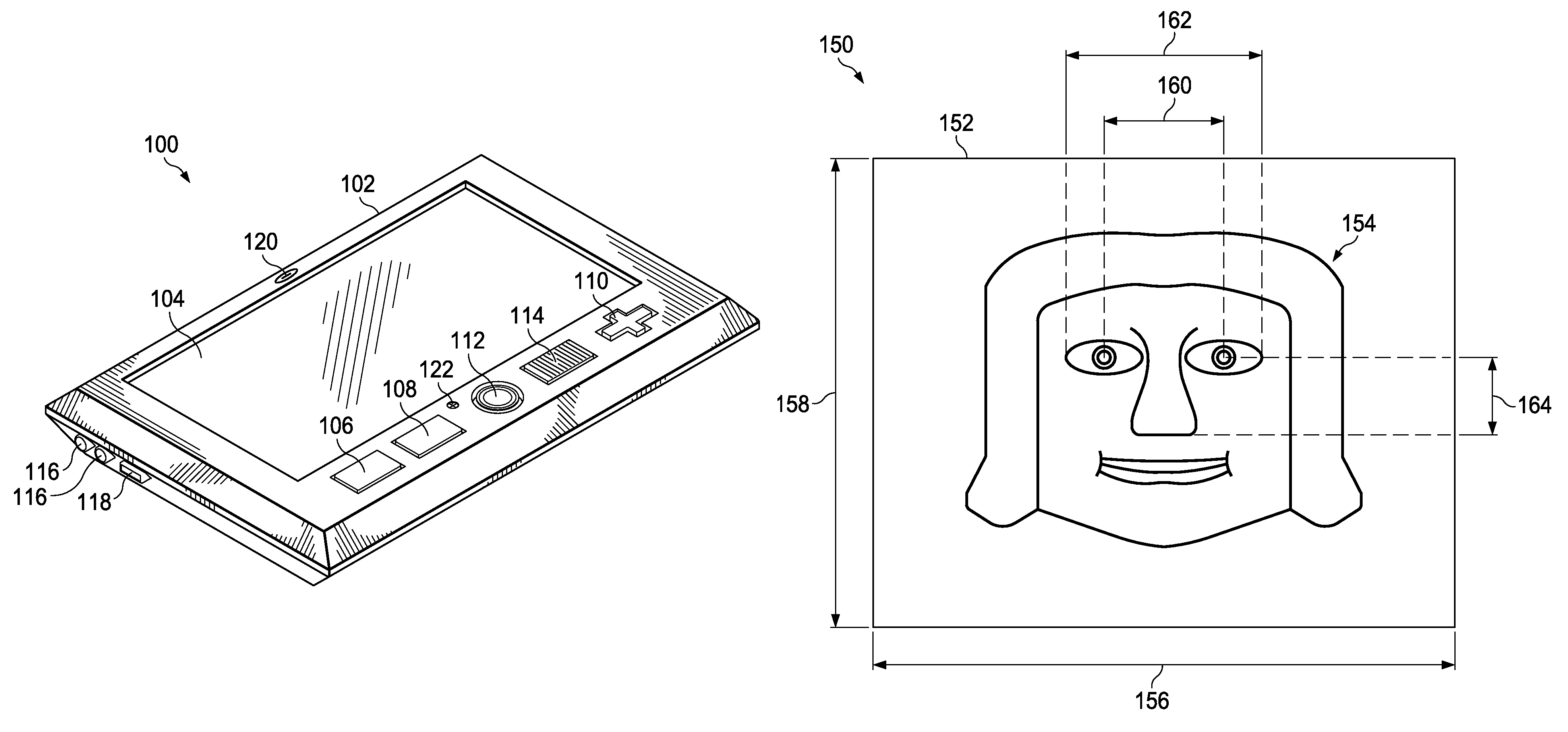
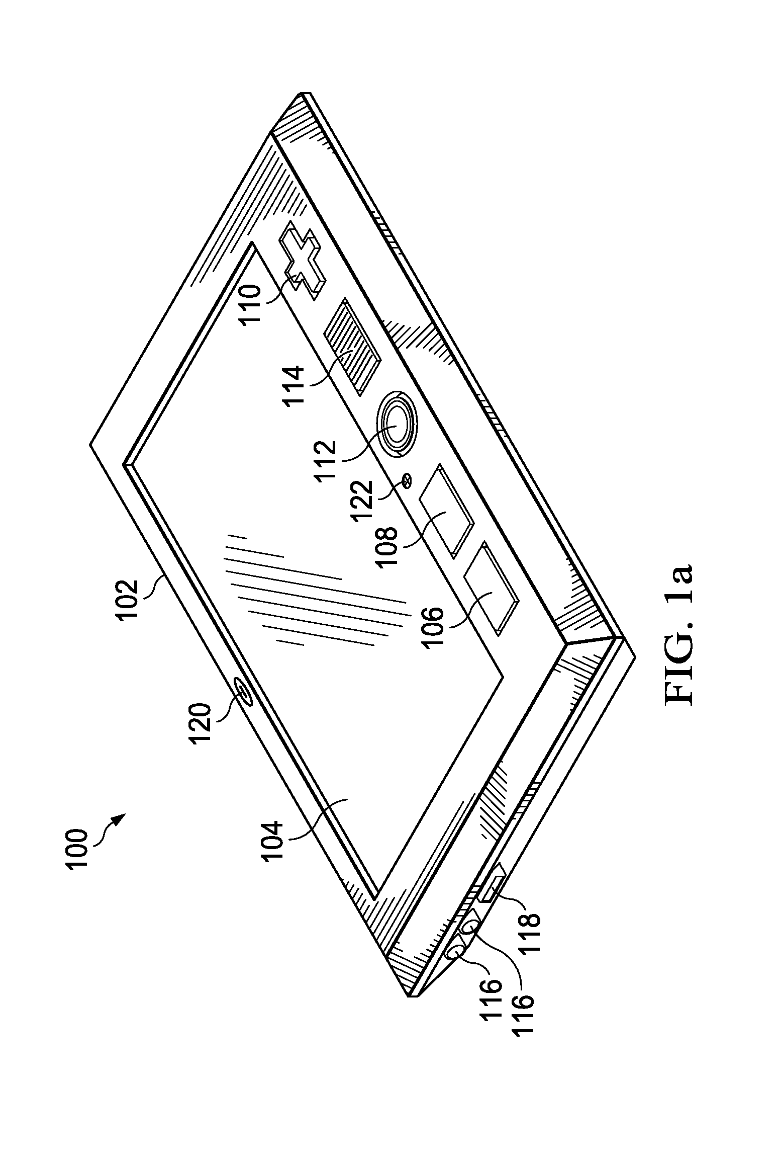
[0028]In FIG. 1a, an electronic handheld device 100 is shown. The handheld device 100 may include a case 102, a display 104, a cursor control 110, a fingerprint sensor 114, a camera 112, a first button 106, a second button 108, a speaker 120, a microphone 122, a power connector 116, and an interface port 118. The display 104 may include touch-screen and / or multi-touch capability so that the handheld device 100 may be controlled by touching the display 104 in various locations or manners within certain timeframes. The fingerprint sensor 114 allows the handheld device 100 to identify the person using it (referred to as a user). Other techniques for positive identification such as voice analysis, passwords, biometric analysis, photographic analysis, and other possible techniques may also be implemented in the handheld device 100. It is also possible to positively identify the specific handheld device 100 that was used to take a specific test by recording an identifying number or code s...


PUM


Abstract

A handheld vision tester and a method of self-testing vision of a user of the handheld vision tester are provided. The method ensures that a display of the handheld vision tester is within an acceptable distance to eyes of the user. Variations of the acceptable distance are compensated for. The method further displays different shapes, either dynamically or statically, on the display to the user. The method also allows for input to the handheld vision tester by the user in response to the different shapes displayed. Results of the self-test are determined from the inputs to the handheld tester by the user.

Description

CROSS-REFERENCE TO RELATED APPLICATION[0001]This application is the National Stage of, and therefore claims the benefit of, International Application No. PCT / US2010 / 034084 filed on May 7, 2010, entitled “Shape Discrimination Vision Assessment System,” which was published in English under International Publication Number WO 2010 / 132304 on Nov. 18, 2010, and has a priority date of May 9, 2009 based on provisional application No. 61 / 176,885 filed by Michael Bartlett, et al. and also has a priority date of Oct. 13, 2009 based on provisional application No. 61 / 251,159 filed by Michael Bartlett, et al. All of the above applications are commonly assigned with this National Stage application and are incorporated herein by reference in their entirety.TECHNICAL FIELD OF THE INVENTION[0002]This invention relates to techniques for the design and implementation of a vision testing and assessment system.BACKGROUND OF THE INVENTION[0003]Vision assessment today is most commonly carried out either w...

Claims


Application Information

Patent Timeline
Patent Type & Authority Patents(United States)
IPC IPC(8): A61B3/10A61B3/032A61B3/00A61B3/12A61B3/11
CPCA61B3/032A61B3/0033A61B3/1225A61B3/111A61B3/02A61B3/028A61B3/0041A61B3/0025A61B3/0058
Inventor BARTLETT, MICHAELWANG, YI-ZHONG
Owner GENENTECH INC
Why Eureka
Try Eureka