Forming apparatus, shoe thereof and forming method

a technology of forming apparatus and forming method, which is applied in the direction of metal rolling arrangement, etc., can solve the problems of difficult to obtain the desired dimensional accuracy of the product, the influence of cross section forming, and the complexity of the elastic recovery deformation section of the product, etc., to achieve the effect of reducing traveling resistance, reducing driving energy, and exceptionally lowering bearing pressur

Active Publication Date: 2015-10-13
NAKATA MFG
View PDF14 Cites 4 Cited by
  • Summary
  • Abstract
  • Description
  • Claims
  • Application Information

AI Technical Summary

Benefits of technology

[0038]In the present invention, since the forming apparatus is employed with a structure using a turning unit formed with an endless shoe block train that is formed by connecting together many shoes each having die with circular curved surfaces so as to be continuously movable on an endless track with the pass directed outward, and the same radius of curvature and the same length as those of a prescribed circular arc part of a virtual circle having an assumed huge diameter are given to an endless track surface of a forming block which abuts on the material to be formed to realize, so to speak, the use of a forming roll having the huge diameter, a continuity and a high productivity which are features of the conventional forming roll are maintained and the material to be formed can be two-dimensionally deformed substantially in the same way as that of the press forming.
[0039]Since the forming apparatus and the forming method according to the present invention have the above-described structure, the forming apparatus and the forming method exhibit following operational effects. (1) An additional distortion due to the three-dimensional deformation applied to the material to be formed is suppressed to a small value as low as possible, and a distribution of the residual stress is uniform. (2) A relative slip due to a peripheral speed difference between a forming tool and the material to be formed hardly occurs. (3) Since a contact area is wide and the occurrence of the peak of the contact stress when the material to be formed advances is suppressed, a bearing pressure is exceptionally lowered. (4) A traveling resistance is greatly reduced and the driving energy is greatly reduced.
[0040]Accordingly, the forming apparatus and the forming method according to the present invention can drastically improve the above-described disadvantages in the conventional roll forming and exhibit following operational effects. (1) The dimensional accuracy, the surface quality and the intrinsic quality of the product are greatly improved. (2) Ranges of forming (a ratio of thickness to outside diameter or a formable material) are enhanced. (3) A cost of the forming tool is reduced and the life of the forming tool is greatly extended. (4) An energy-saving product can be manufactured.

Problems solved by technology

However, not only bending and squeezing within the section as an object of forming, but also various additional deformations and distortions in other directions are generated and accumulated due to the characteristics of the rolls as the forming tool as described above, which frequently gives a serious influence to a forming of the cross section.
Accordingly, for instance, in the above-mentioned sizing process, an elastic recovery deformation in the section of the product becomes extremely complicated.
Thus, the above-described problems peculiar to the forming rolls cannot be solved, for instance, a desired dimensional accuracy of the product is not easily obtained.

Method used


Image

  • Forming apparatus, shoe thereof and forming method
  • Forming apparatus, shoe thereof and forming method
  • Forming apparatus, shoe thereof and forming method

Examples


first embodiment

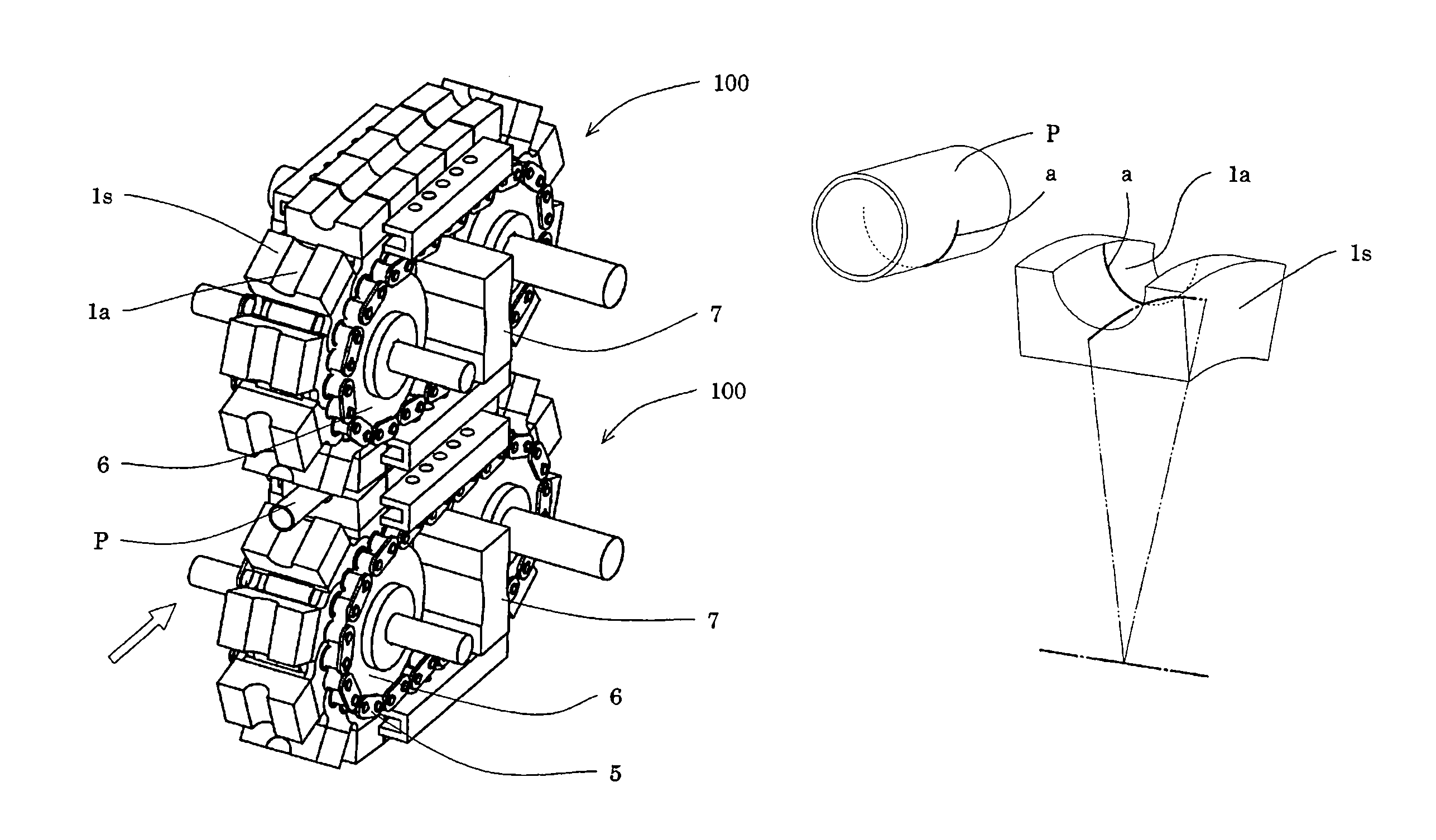
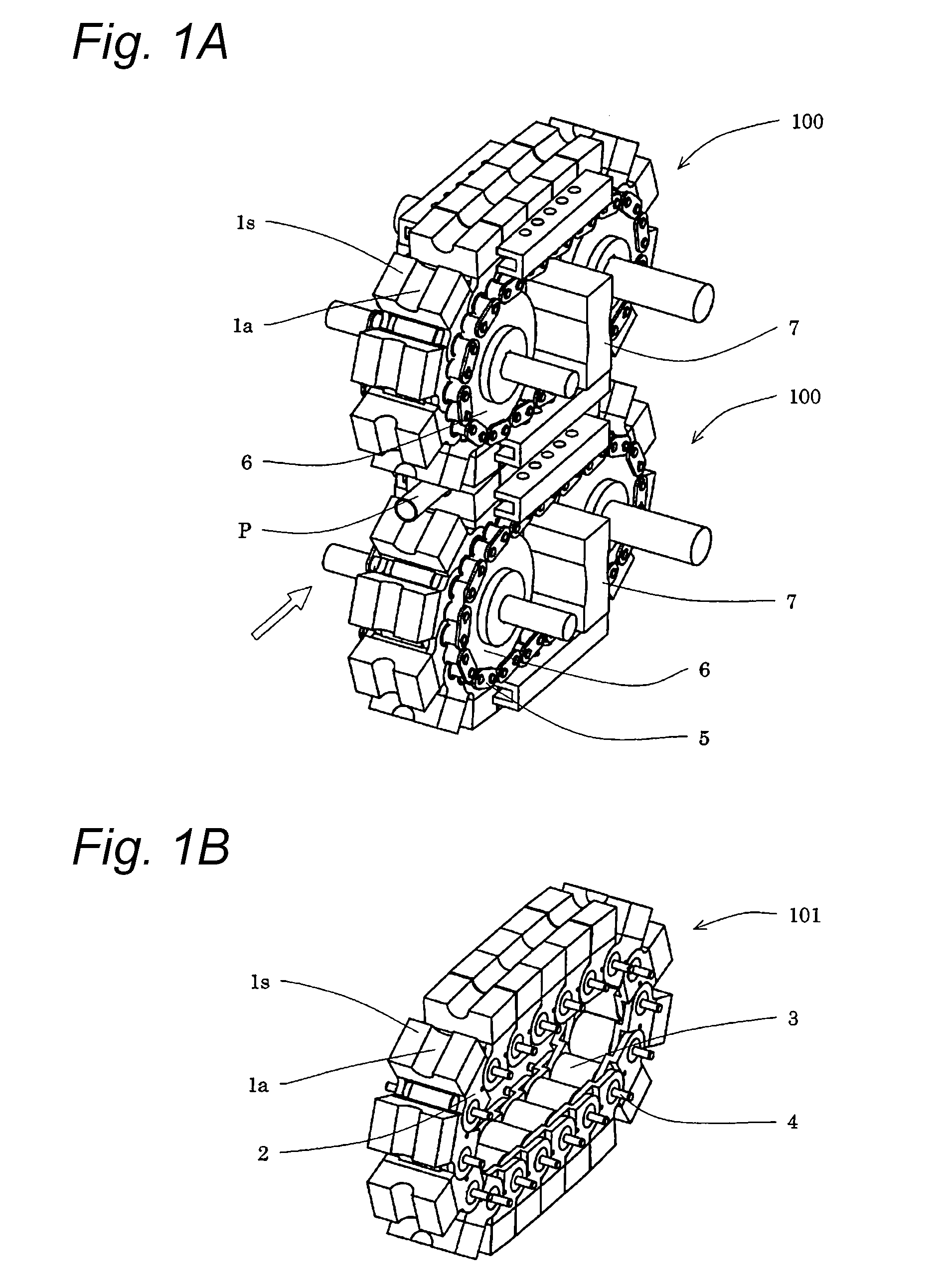
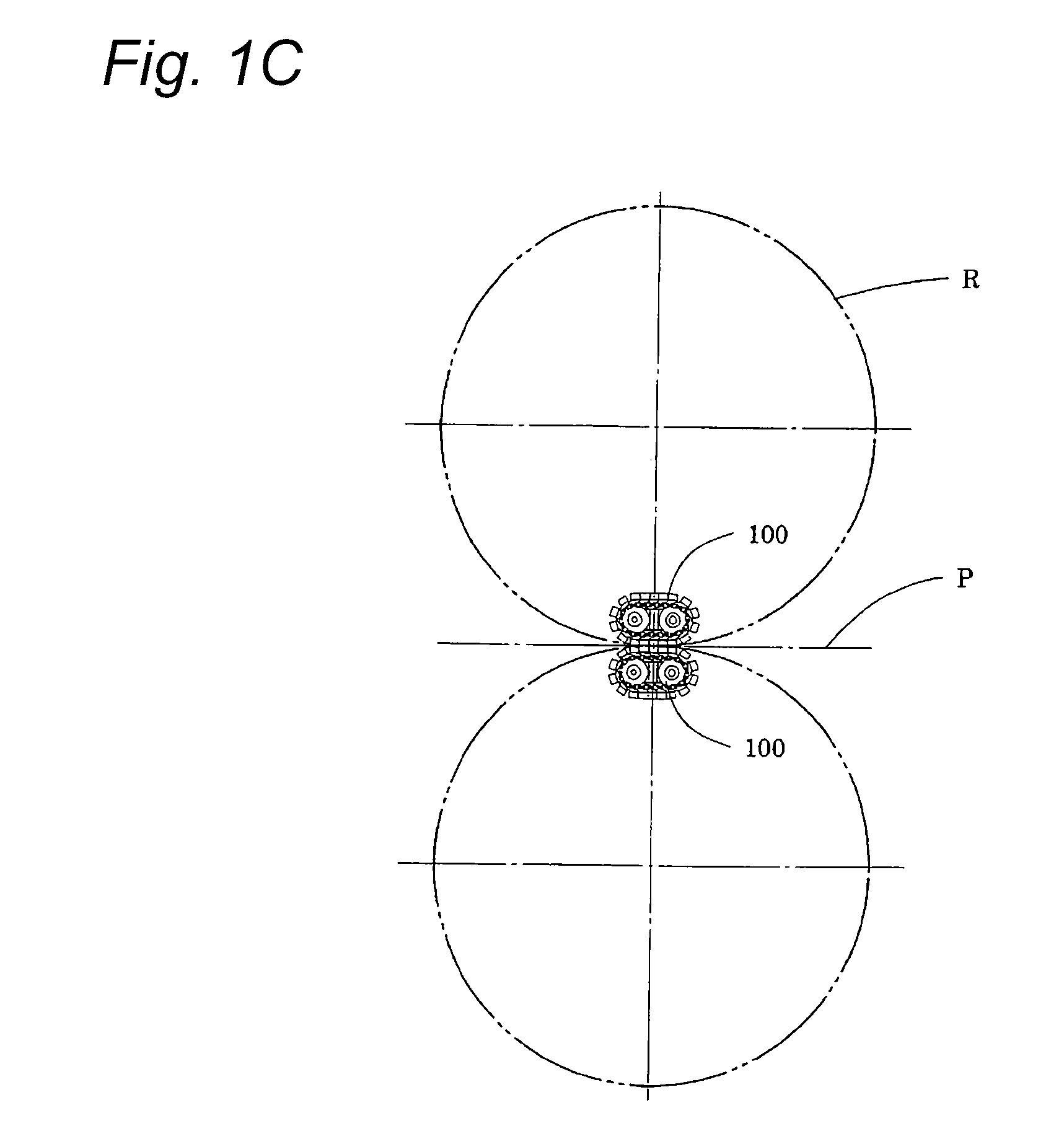
[0077]A forming apparatus shown in FIGS. 2A and 2B has a structure that binds a material pipe 2 to be formed from four directions to size the material to be formed. One pairs of endless shoe block trains 102, 103, 104 and 105 which are opposed and arranged in a vertical direction and a horizontal direction are respectively supported by beams 11, 11, 12 and 12. The beams 11, 11, 12 and 12 are supported by housings 10 and 10 through jacks 13, 14, 15 and 16 for adjusting their supporting positions.

[0078]The endless shoe block trains 102, 103, 104 and 105 are respectively made to be endless by connecting a shoe assembly 20 shown in FIG. 3 by pins 26 and formed so as to freely turn by inserting three ball trains shown in FIG. 6 between the endless shoe block trains and endless track surfaces supported by the beams 11, 11, 12 and 12 to form ball bearing parts. Driving shaft units 17 and 17 drive turning units composed of the endless shoe block trains 102 and 103 opposed and arranged in th...

second embodiment

[0085]A forming apparatus having the same structure as that of the first embodiment is applied to a sizing process of a product having a target diameter of 100 mm and a thickness of 7 mm. A material is hot-rolled steel and a reduction rate is 1%.

[0086]To a forming block of an endless track of the forming apparatus, radii of curvature (2,500 to 20,000 mm) are applied to study a contact state of an endless shoe block train and a material to be formed and a load distribution. Further, as objects to be compared, a sizing device having a conventional four-way roll (a radius of 200 mm) and a device having the same structure as that of this embodiment and a linear forming block are prepared.

[0087]FIG. 12 shows the contact state and the load distribution acting on a material pipe to be formed. An axis of abscissas of this graph indicates a longitudinal distance from a lowermost point (immediately below a roll) of a pressing down operation of a shoe of a turning unit. An axis of ordinates in...

third embodiment

[0089]In the second embodiment, when a material of a material pipe to be formed is changed from ordinary steel to stainless steel to carry out a sizing process, in the case of a conventional roll forming, the occurrence of seizure on the surface of the material pipe due to a relative slip of the material pipe and the forming roll is detected under a non-lubrication. As compared therewith, in the forming apparatus of this embodiment, a seizure does not occur even under the non-lubrication.


PUM

PropertyMeasurementUnit
lengthaaaaaaaaaa
radiusaaaaaaaaaa
diameteraaaaaaaaaa

Abstract

A forming apparatus and method for forming a sectional profile of round tubing, angled tubing or open forming stock without losing the manufacturability of conventional roll forming The forming apparatus comprises individual shoe blocks having a pass on their rotating curved faces. The shoe blocks can be moved in the circumferential direction on an endless track, and are connected to provide the same curvature radius and length as a required arc segment of a virtual large-diameter circle.

Description

TECHNICAL FIELD[0001]Relating to a new apparatus and a method for forming an opening section member having various kinds of sectional shapes, such as a round pipe or a rectangular pipe, from a metal coil or a strip material with a prescribed length, this invention is a forming apparatus, a shoe thereof and a forming method using a turning unit in which a shoe-blocks train formed by using the plural shoes of which forming dies provided outward surface and moves on an endless track to realize a forming operation just like that obtained by using forming rolls having a huge diameter.BACKGROUND ART[0002]In general, as a continuous manufacturing process of long metal products, forming rolls are ordinarily used. A typical process among them represented by an electric-resistance-welded pipe process ordinarily includes a pre-process for rewinding a metal coil as a material to supply the metal coil to a forming process, an initial forming process carried out by break down rolls, cluster rolls...

Claims


Application Information

Patent Timeline
Patent Type & Authority Patents(United States)
IPC IPC(8): B21C37/08B21D5/10B21C37/083
CPCB21C37/08B21D5/10B21C37/083
Inventor WANG, FEIZHOUNAKANO, TOMOYASUINOKUMA, AKINORIYIN, JILONGAKAI, TERUTOMO
Owner NAKATA MFG
Why Eureka
Try Eureka