

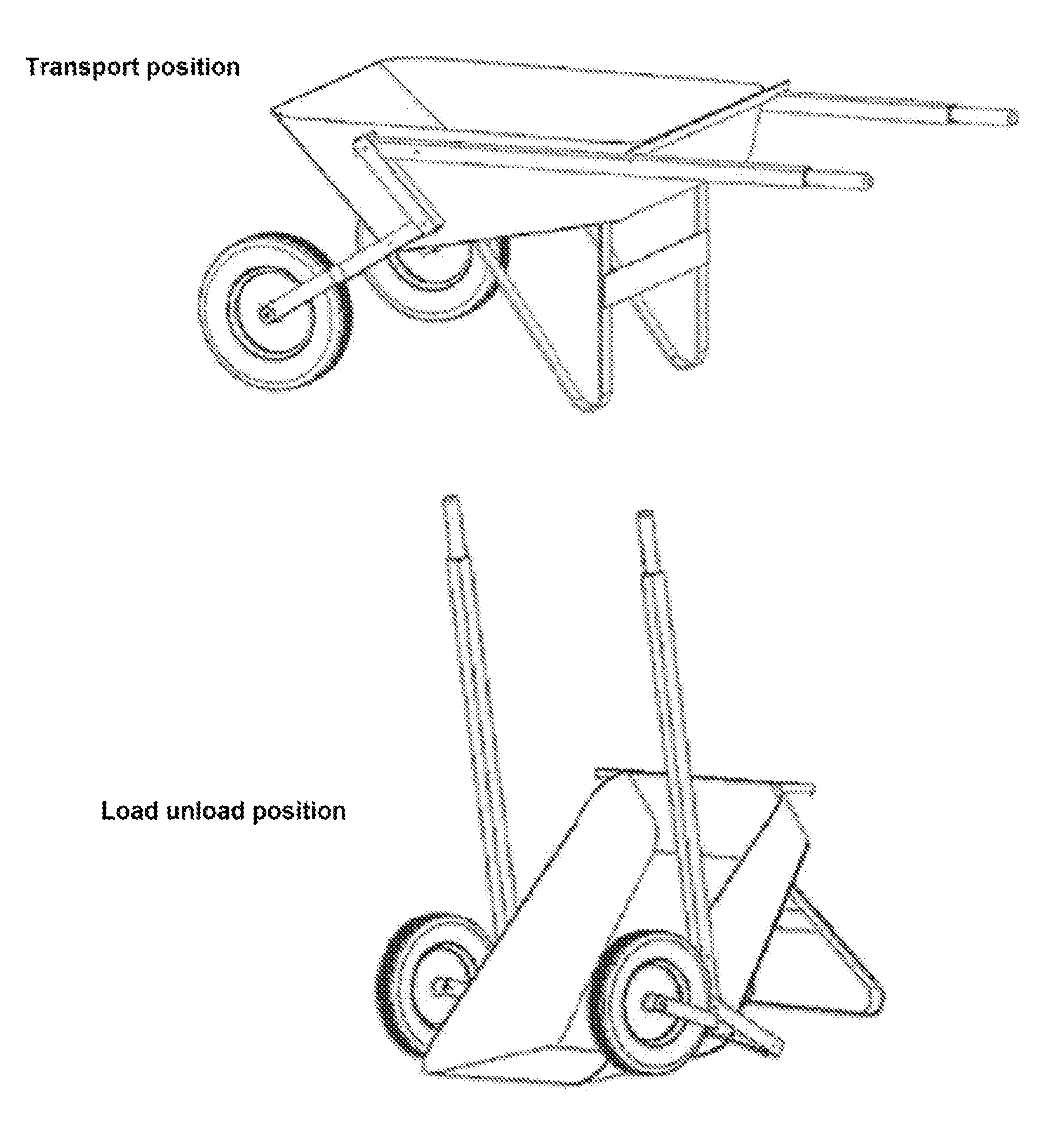
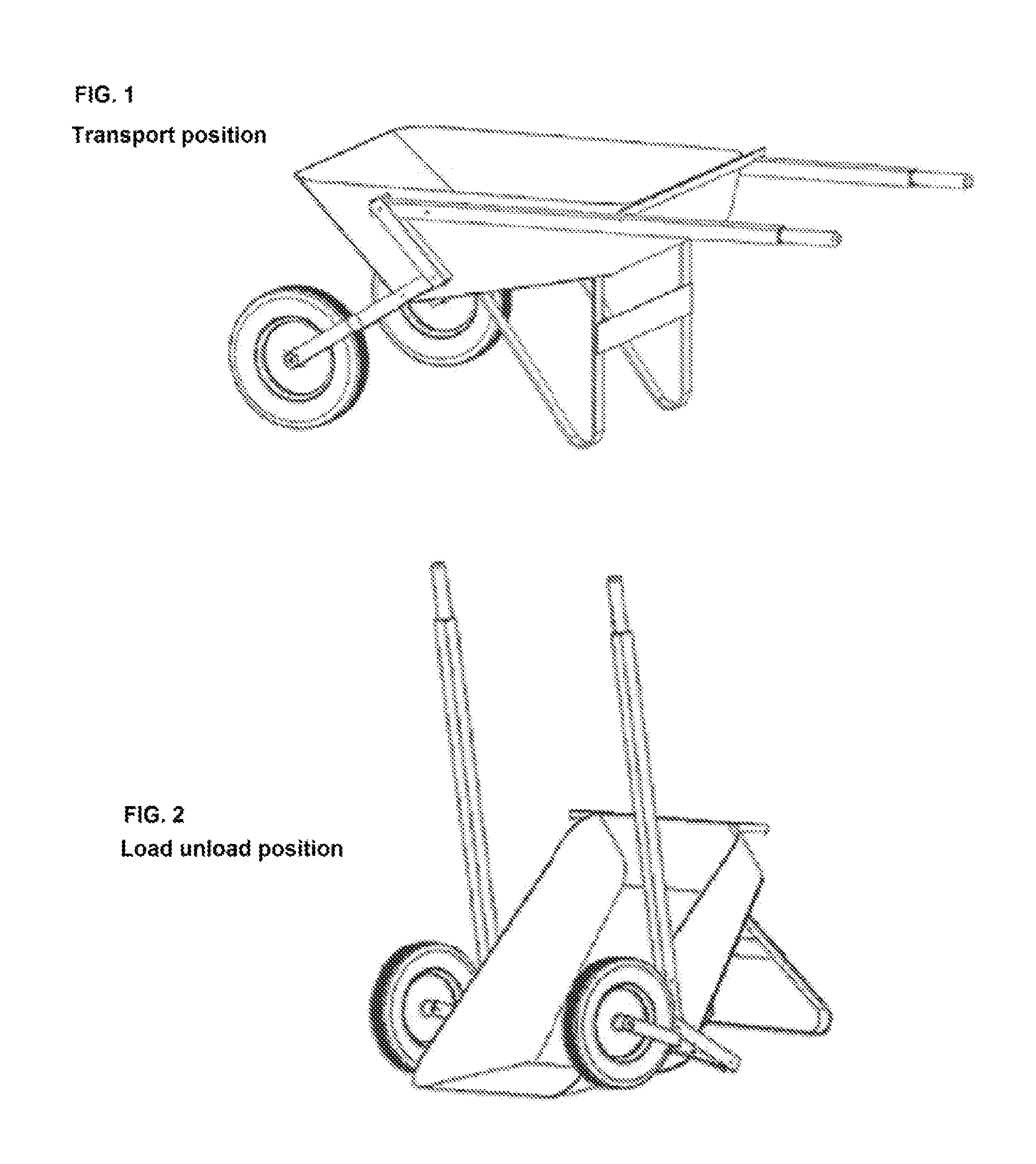
Kneeling wheelbarrow
a wheelbarrow and kneading technology, applied in the field of manual load lifting and transporting devices, can solve the problems of difficult lifting of the load to fill and empty the wheelbarrow, difficult to dump in measured amounts, and the prior art wheelbarrow requires a considerable force. , to achieve the effect of less physical for
- Summary
- Abstract
- Description
- Claims
- Application Information
AI Technical Summary
Benefits of technology
Problems solved by technology
Method used
Image

Examples
Embodiment Construction
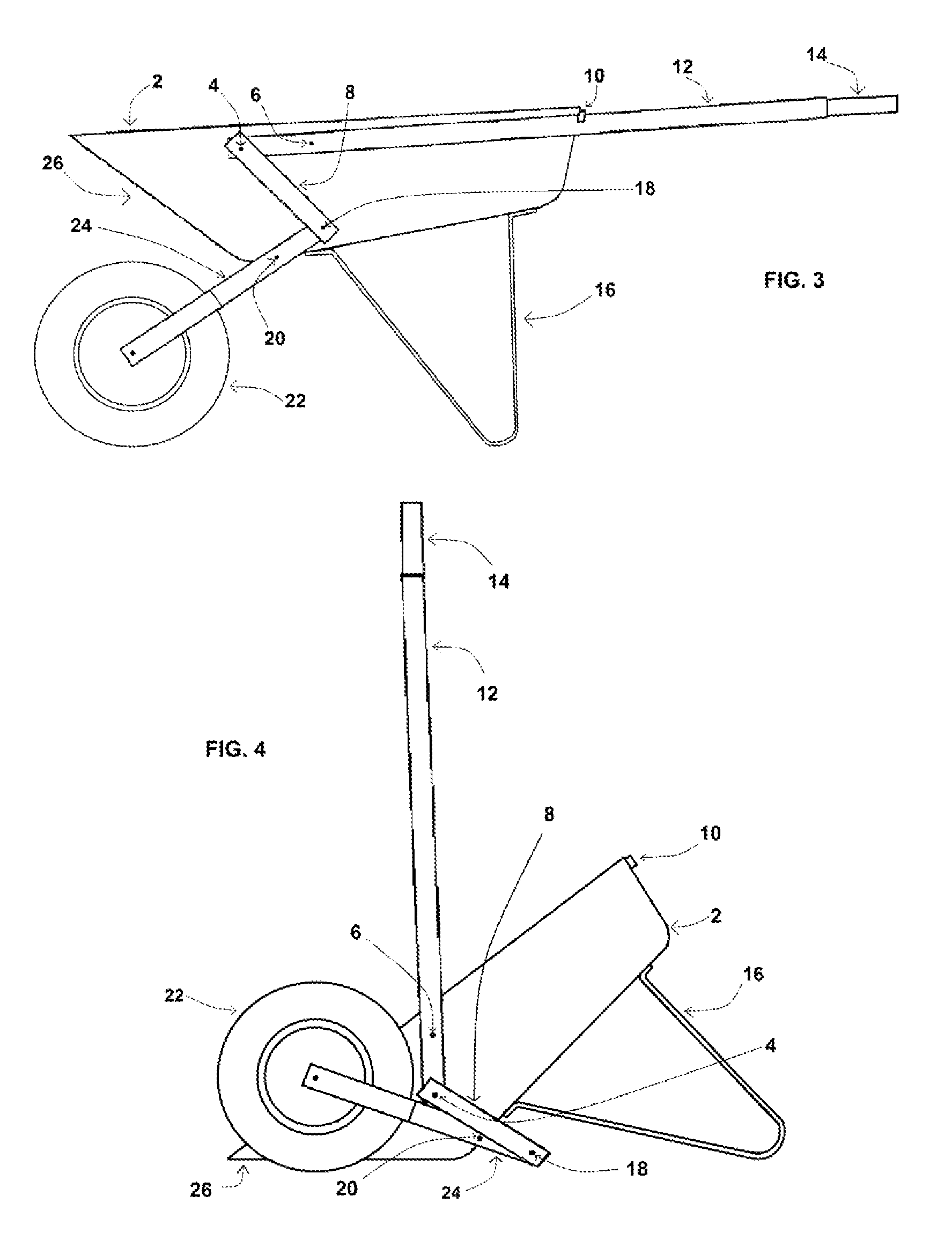
[0012]A wheelbarrow incorporating at least one lever handle (12), that rotates on the handle fixed pivot pin (6), a floating link (8) attached at one end of the lever handle (12) in a manner to allow rotation in the same plane as the lever handle (12), a wheel strut (24) that is connected at one end to the floating link (8) opposite of the lever handle (12). The wheel strut (24) also rotates about the strut fixed pivot pin (20) in the same plane as the lever handle (12).
[0013]In the preferred configuration the lever handle, floating link, and the wheel strut attachment is as described herein and illustrated in the views, with the wheel strut rotating in the opposite direction from the lever handle. The preferred material for manufacture is steel, although other materials such as wood may be contemplated. Two assemblies as described above attached to each side of the wheelbarrow provide optimum performance. The location of the attaching pieces can be altered to produce different rota...
PUM
 Abstract
Description
Claims
Application Information