
Friction drive lift
a technology of friction drive and lift, which is applied in the direction of railway tracks, ways, locomotives, etc., can solve problems such as mechanical complexity
- Summary
- Abstract
- Description
- Claims
- Application Information
AI Technical Summary
Benefits of technology
Problems solved by technology
Method used
Image

Examples
first embodiment
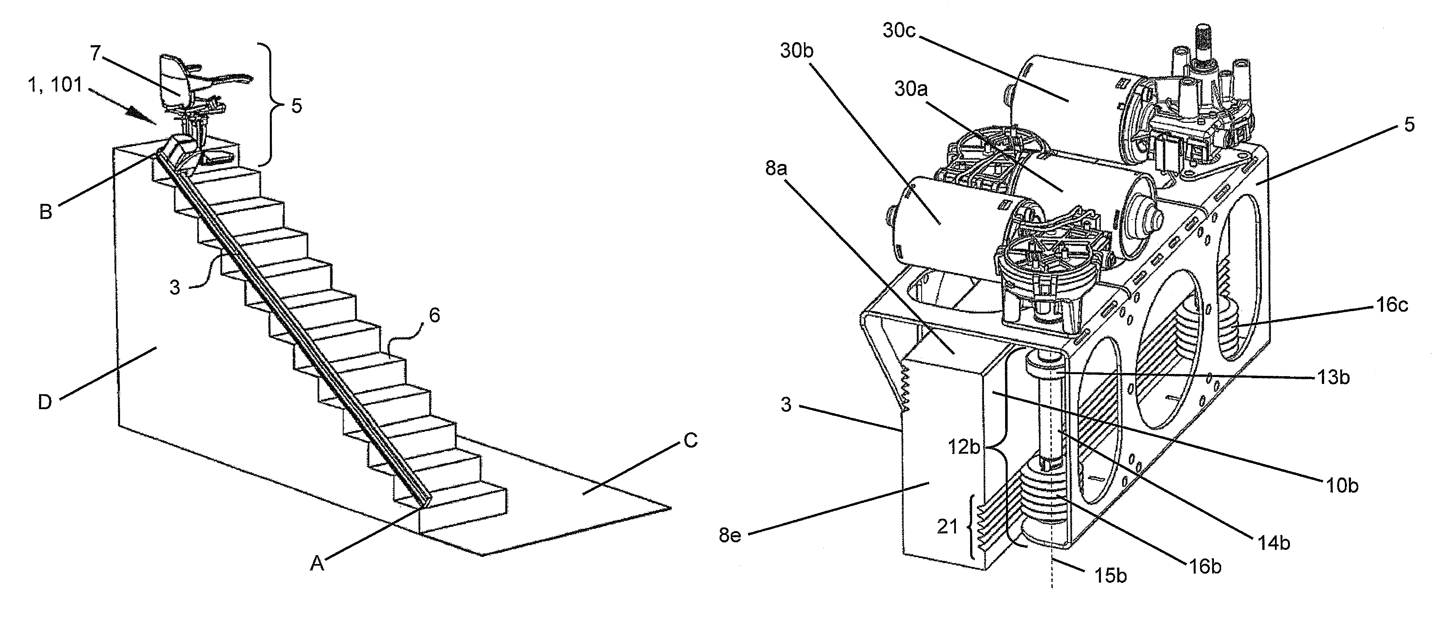
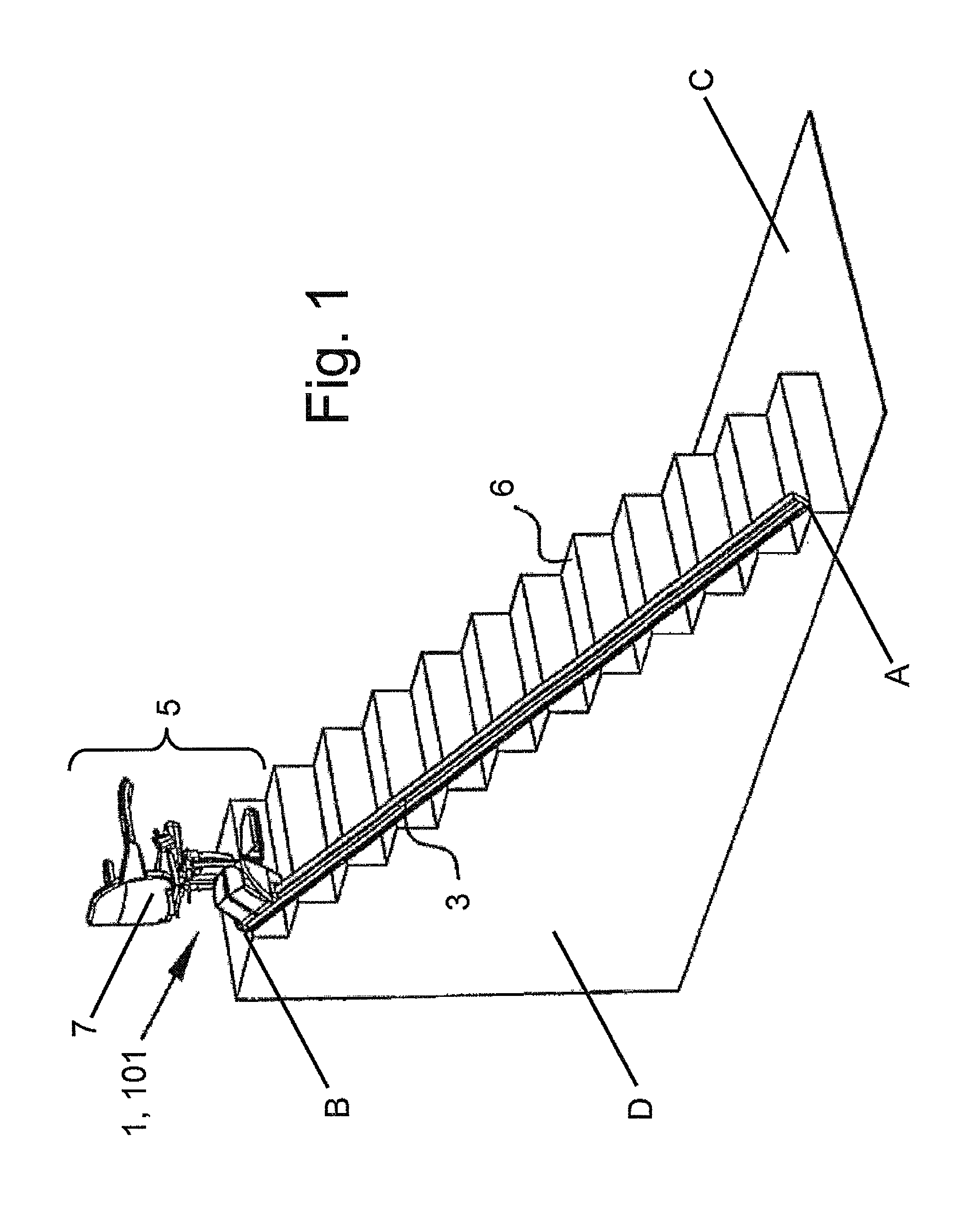
[0076]FIG. 1 shows a stair lift 1 according to the invention and comprises a guide 3 and a carriage 5. The guide 1 is arranged along a staircase 6. The staircase may be used by a person to transport himself from a start point to an end point or vice versa. In FIG. 1 it is shown that the guide 1 is arranged from start point A to start point B. When the person is handicapped or for other reasons unable to use the staircase 6, the person may use the stair lift 1 to be transported from start point A to end point B or vice versa. In this embodiment the stair lift 1 further comprises a load carrier 7 in the form of a seat. The load carrier 7 may be used by the person to sit on. Particularly, when the person is seated in the load carrier 7 the person may be transported between start point A and end point B or vice-versa. Alternatively, the load carrier 7 is a flat platform for carrying a wheel chair or goods. In FIG. 1 the guide 3 is shown as a straight rail.
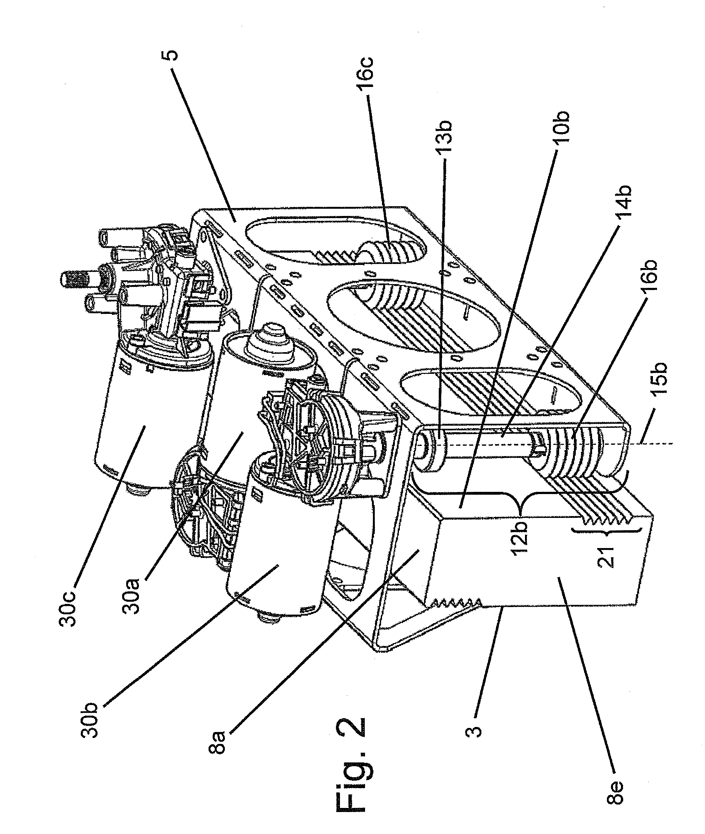
[0077]FIG. 2 shows a perspectiv...
second embodiment
[0101]In this second embodiment the frame 105 is provided with four rollers. Two rollers, being a first roller 112a and a fourth roller 112d, are arranged in frictional engagement with the first side running surface 10a. This can be seen best in FIG. 9. Two other rollers, being a second roller 112b and a third roller 112c are arranged in frictional engagement with the second side running surface 10b. These can be seen best in FIG. 11. Note, that the first side running surface 10a and the second side running surface 10b are opposing sides. Therefore, the first roller 112a and the fourth roller 112d are arranged on opposing sides with respect to the second roller 112b and the third roller 112d. The fact that four rollers are arranged with two rollers on opposing sides has as advantage that forces and moments of forces originated by the load carrier 7 can be distributed safely via the rollers 112a, 112b, 112c, 112d to the guide 3 which will be explained below.
[0102]The load carrier 7 i...
PUM
 Abstract
Description
Claims
Application Information