Method for reconstructing a current block of an image and corresponding encoding method, corresponding devices as well as storage medium carrying an images encoded in a bit stream

a technology of image and current block, applied in the field of prediction image block encoding and reconstruction, can solve problems such as insufficient efficiency (in terms of rate distortion performance), and achieve the effect of reducing the encoding cos

Active Publication Date: 2015-10-13
INTERDIGITAL MADISON PATENT HLDG
View PDF10 Cites 3 Cited by
  • Summary
  • Abstract
  • Description
  • Claims
  • Application Information

AI Technical Summary

Benefits of technology

[0013]Thus, the inventors propose to improve the principle of the geometry-adaptive block partitioning for image block coding by steps which enable extraction of more complex Geometry contours than straight lines and further provide a reduction of the encoding cost. The principle is to exploit the implicit Geometry in the source images, by extracting the Geometry information from the images, rather than to determine the Geometry parameters independently from the source image characteristics.

Problems solved by technology

Despite the adaptation flexibility of quad-tree partitions, a recent study by C. Dai, O. Escoda, P. Yin, X. Li, C. Gomila, “Geometry-Adaptive block Partitioning for Intra Prediction in Image & Video Coding,” Image Processing, 2007, ICIP 2007, IEEE International Conference on Volume 6, Sep. 16, 2007-Oct. 19, 2007, pp VI-85-VI-88, has shown that these are not efficient enough (in terms of rate distortion performance) when images can be locally modelled as 2D piece wise-smooth signals.

Method used


Image

  • Method for reconstructing a current block of an image and corresponding encoding method, corresponding devices as well as storage medium carrying an images encoded in a bit stream
  • Method for reconstructing a current block of an image and corresponding encoding method, corresponding devices as well as storage medium carrying an images encoded in a bit stream
  • Method for reconstructing a current block of an image and corresponding encoding method, corresponding devices as well as storage medium carrying an images encoded in a bit stream

Examples


first embodiment

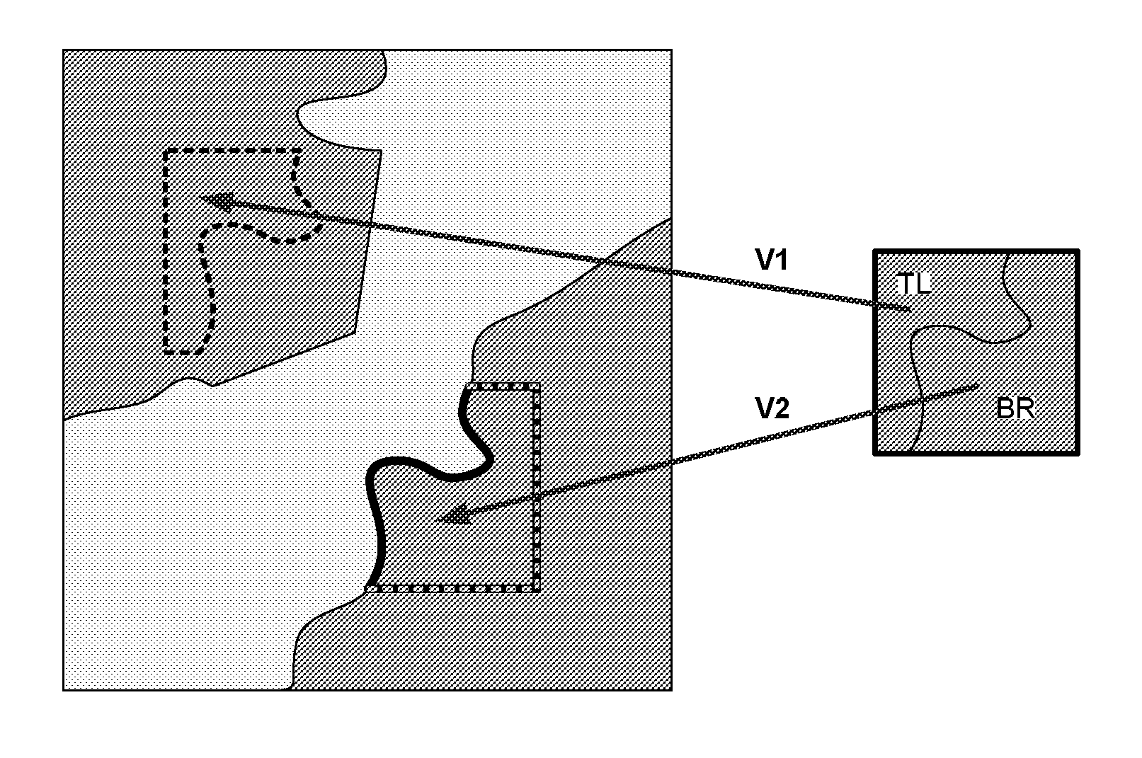
[0043]The first embodiment is related to encoding of a block which exhibits a single edge separating the block to-be-encoded into two segments. Each of the two segments is predicted by one reference block, thus there are two blocks determined for prediction which are referenced by two motion vectors. The two referenced blocks are chosen such that one of them not only predicts the segment but also the single edge. That is, at decoder side the one reference block can be segmented for determining the edge which is then used for determining the segment predictions using the one and the other block. For providing the decoder with information required for determining which of the two reference blocks to use for edge prediction and for further determining which of the two segments separated by the edge determined in the edge predicting reference block to-be-used, an encoding order of the two motion vectors and a flag is used.

[0044]Either, the block referenced by the motion vector at a pred...

second embodiment

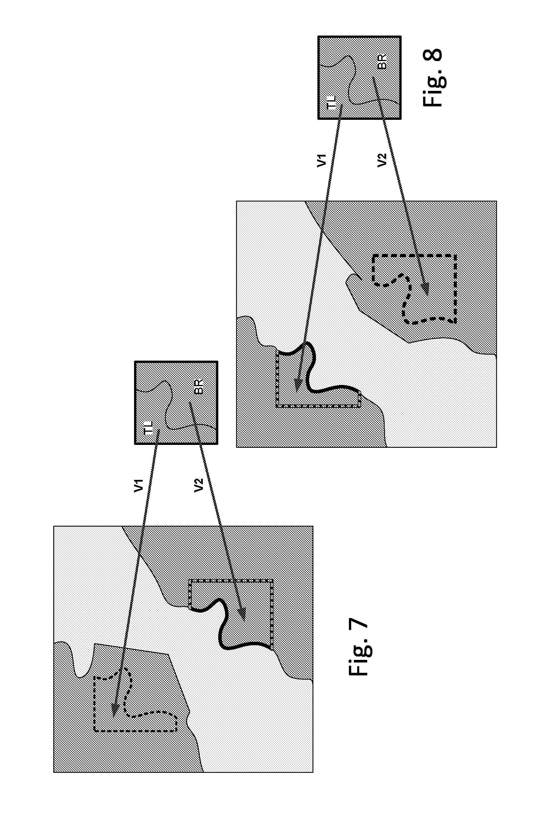
[0046]The second embodiment is related to encoding of a block which depicts two edges separating the block to-be-encoded into three segments. Each of the three segments is predicted by one reference block, thus there are three blocks determined for prediction which are referenced by three motion vectors. The three referenced blocks are chosen such that each of two of them not only predicts one of the segments but also one of the edges. That is, at decoder side these two reference blocks can be segmented for determining the edges which are then used for determining the segment predictions using these two and the one remaining reference block. For providing the decoder with information required for determining which of the three reference blocks to use for edge prediction and for further determining which of the segments separated by the predicted edges to-be-used, an encoding order of the three motion vectors and two flags are used.

[0047]For instance, the first motion vector in encod...

third embodiment

[0050]The third embodiment is also related to encoding of a block which depicts two edges separating the block to-be-encoded into three segments. According to the third embodiment, the three referenced blocks are chosen such that one of them not only predicts one of the segments but also both edges. That is, at decoder side this one reference block can be segmented for determining the edges which are then used for determining the segment predictions using these two and the one remaining reference block. For providing the decoder with information required for determining which of the three reference blocks to use for edge prediction and for further determining which of the segments separated by the predicted edges to-be-used, an encoding order of the three motion vectors and two flags are used.

[0051]For instance, the first motion vector in encoding order references the block predicting the two edges and the flags signals which of the resulting three segments separated by said edges t...


PUM


Abstract

The invention is made in the field of image block encoding and reconstruction. A method for reconstructing a current block of an image is described, the current block being encoded using predictive encoding of segments resulting from geometry adaptive block partitioning of said current block. After decoding encoded data comprising at least one flag and motion vectors, wherein blocks referenced by the motion vectors are used for prediction of segments of the current block, the at least one flag and an encoding order of the motion vectors in the encoded data is used for determining which of the referenced blocks exhibits a geometry that matches the geometry of the current block and for determining a segment of the determined block, wherein prior to determining the segment, the determined block is geometry adaptive block partitioned into segments from which the segment is determined for predicting one of the segments of the current block.

Description

[0001]This application claims the benefit, under 35 U.S.C. §365 of International Application PCT / EP2011 / 063623, filed Aug. 06, 2011, which was published in accordance with PCT Article 21(2) on Feb. 23, 2012 in English and which claims the benefit of European patent application No. 10305898.8, filed Aug. 19, 2010.TECHNICAL FIELD[0002]The invention is made in the field of predictive image block encoding and reconstruction wherein segments resulting from geometry adaptive block partitioning are predicted.BACKGROUND OF THE INVENTION[0003]Many modern video coding strategies, such as the H.264 / AVC standard, use quadtree-based partition structures for coding macro-blocks. Such a structure allows the coding algorithm to adapt to the complicated and non-stationary nature of natural images. Despite the adaptation flexibility of quad-tree partitions, a recent study by C. Dai, O. Escoda, P. Yin, X. Li, C. Gomila, “Geometry-Adaptive block Partitioning for Intra Prediction in Image & Video Coding...

Claims


Application Information

Patent Timeline
Patent Type & Authority Patents(United States)
IPC IPC(8): G06K9/36G06T9/00G06K9/46H04N19/543H04N19/176H04N19/159
CPCG06T9/004H04N19/543H04N19/176H04N19/159H04N19/119
Inventor BORDES, PHILIPPETHOREAU, DOMINIQUEVIERON, JEROMEFRANCOIS, EDOUARD
Owner INTERDIGITAL MADISON PATENT HLDG
Why Eureka
Try Eureka