High frequency coaxial connector

a coaxial connector and high frequency technology, applied in the direction of coupling devices, two-part coupling devices, electrical equipment, etc., can solve the problems of affecting and the axial direction of compensation is not possible, and the design of the connector parts is comparatively complicated

Active Publication Date: 2015-10-13
HUBERSUHNER AG
View PDF26 Cites 4 Cited by
  • Summary
  • Abstract
  • Description
  • Claims
  • Application Information

AI Technical Summary

Benefits of technology

[0014]It is an object of the invention to provide a connector by means of which high-frequency plug-in connections between multiple dispersed points on a printed circuit board (PCB), and, for example, a front of a module parallel thereto may be easily and inexpensively manufactured. A further object of the invention is to provide a connector which is able to compensate for positional inaccuracies.
[0022]In one embodiment, the connecting sleeve has an inwardly directed protrusion having a conical guide surface which opens into a connecting opening that is suitable for accommodating a pin-shaped second connector part. The outer conductor may have a contact surface which may be used for contacting a printed conductor on a printed circuit board. Alternatively or additionally, the outer conductor may be operatively connected to an electrically conductive seal which is used for contacting a printed conductor on a printed circuit board. The connector according to the invention provides a good high-frequency shield, and at the same time allows positional inaccuracies to be compensated for in the axial and radial directions. In one embodiment of the coaxial connector which is suitable for bridging a distance of 9 mm between a printed circuit board (PCB) and a device front plate, an axial offset of up to 1 mm and a radial offset of up to 0.5 mm may be compensated for. Other areas are possible with an appropriate configuration. The connector according to the invention is particularly suited for an inexpensive “floating” connection of high-frequency components on a printed circuit board. It is generally necessary only to solder a simple inner conductor pin to the printed circuit board. The high-frequency shield may be optimally ensured, even when there are geometrical misalignments between the elements to be contacted. In one field of application, a filter is in direct operative connection with a printed circuit board of a duplexer in a mobile wireless base station.

Problems solved by technology

All three connector parts have a comparatively complicated coaxial design.
Due to the design, no compensation is possible in the axial direction.
The connector parts have a comparatively complicated, cost-intensive design.
The connector has a comparatively complicated design.
The connector is not suitable for transmitting high frequencies.
All of the connectors have a comparatively complicated design.

Method used


Image

  • High frequency coaxial connector
  • High frequency coaxial connector
  • High frequency coaxial connector

Examples


Embodiment Construction

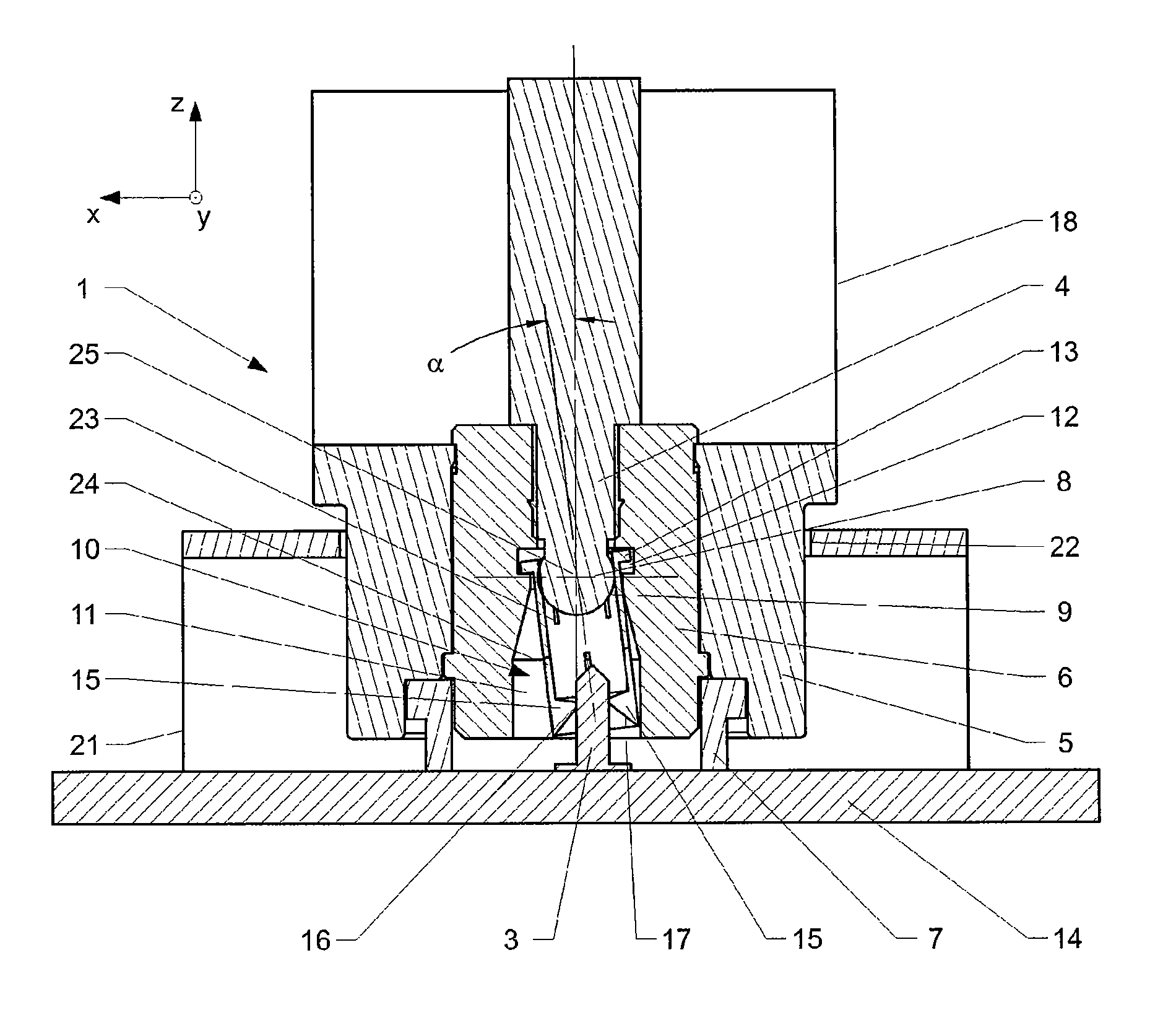
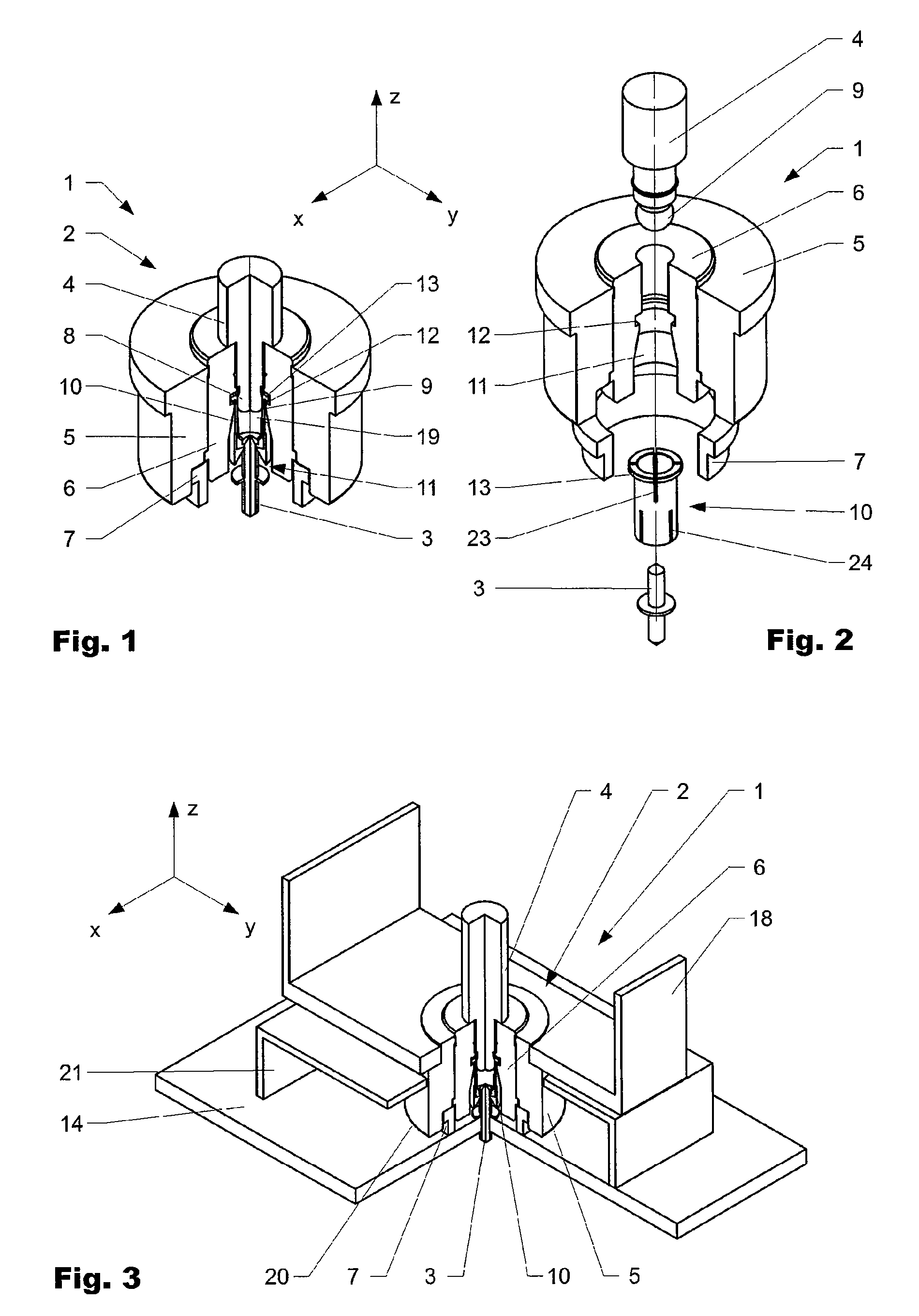
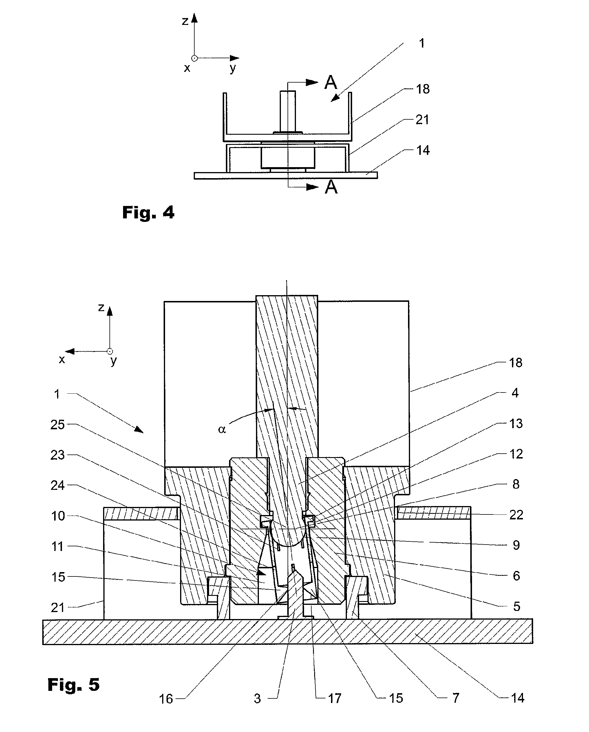
[0031]FIG. 1 shows a first embodiment of a coaxial connector 1 according to the invention in a perspective illustration obliquely from above. FIG. 2 shows the same coaxial connector 1 in an exploded illustration. FIG. 3 shows the coaxial connector 1 in the mounted state. FIG. 4 shows the coaxial connector 1 in a side view, and FIG. 5 shows the coaxial connector 1 in a sectional illustration along the section line AA. FIG. 6 shows a second embodiment of a coaxial connector 1 according to the invention in a side view, and FIG. 7 shows the coaxial connector 1 in a sectional illustration along the section line BB. Corresponding areas are provided with the same reference numerals in the individual embodiments.

[0032]FIGS. 1 and 2 illustrate the coaxial connector 1 in a cutaway view to provide better visibility of the interior of the coaxial connector 1.

[0033]The coaxial connector 1 is composed of a first connector part 2 and a second connector part 3. The first connector part 2 is affixed...


PUM


Abstract

The invention relates to a high frequency coaxial connector (1) having a first and a second connector part (2, 3). The first connector part (2) comprises an outer conductor (5) and an inner conductor (4) held relative to said outer conductor by means of an insulator (6) and disposed in an opening (11) of the insulator (6). The inner conductor (4) comprises an end piece (8) that is electrically conductively and operatively connected to a connector sleeve (10). The connector sleeve (10) is mechanically operatively connected to the insulator (6) by means of first operative connection means (12, 13), so that the connector sleeve (10) can be tilted relative to the inner conductor (4). An axial displacement can be made possible by means of the active connection to the second connector part (3).

Description

BACKGROUND OF THE INVENTION[0001]1. Field of the Invention[0002]The present invention relates to a high-frequency coaxial connector, in particular a coaxial connector part for a high-frequency coaxial connector, according to the preamble of the independent patent claim.[0003]2. Discussion of Related Art[0004]Various high-frequency coaxial connectors for the operative connection of printed circuit boards are known from the prior art.[0005]U.S. Pat. No. 4,925,403 was filed in 1988 in the name of Gilbert Engineering Co. US'403 discloses a coaxial connector composed of two connector parts and a transition piece situated in between same. All three connector parts have a comparatively complicated coaxial design. The connector is designed in such a way that a certain lateral offset may be compensated for. Due to the design, no compensation is possible in the axial direction. The transition piece is detachably snapped into the first and the second connector parts.[0006]EP 0793299 was filed ...

Claims


Application Information

Patent Timeline
Patent Type & Authority Patents(United States)
IPC IPC(8): H01R24/40H01R13/631H01R24/50H01R103/00
CPCH01R24/40H01R13/6315H01R2103/00H01R24/50
Inventor WAGNER, MARTIN
Owner HUBERSUHNER AG
Why Eureka
Try Eureka