Method and system for stimulating a heart

a heart and system technology, applied in the field of implantable medical devices, can solve the problems of difficult to continuously optimize the vv delay in patients treated with cardiac resynchronization therapy (crt), neither echocardiography nor invasive pressure measurements can be performed,

Active Publication Date: 2015-10-20
ST JUDE MEDICAL
View PDF21 Cites 9 Cited by
  • Summary
  • Abstract
  • Description
  • Claims
  • Application Information

AI Technical Summary

Benefits of technology

[0019]In the embodiments based on retrograde conduction, it is necessary to identify a time window when the AV node is capable of retrograde conduction. Retrograde P-waves are, for example, frequently seen after a PVC (Premature Ventricular Contraction). After an atrial contraction, the stimulation device waits for an anterograde ventricular depolarization. After short period of time, a stimulation pulse is delivered in RV or LV. A depolarization wave is spread across the myocardium and eventually reaches the AV node. If properly timed, this will result in a retrograde conduction through the AV node and a propagated atrial wave. After some time, this retrograde P-wave will be detected by an atrial electrode. The time from RV or LV to RA / LA is measured and registered. This process is repeated but the stimulation is delivered in the other ventricle. The new V-to-A time is registered and compared with the former one. The propagation time spent in the atrium is equal in both cases, so the remaining difference is due to different propagation times in the ventricles. If it takes longer for a LV stimulation to reach the AV node (i.e. for depolarization wave resulting from a stimulation in LV), LV should be stimulated first and the right ventricle should be stimulated with a time difference equal to the aforementioned time difference.
[0020]When optimizing based on V-to-A times, it is essential that the P-wave detected as retrograde is not a sinus node released P-wave. In order to prevent this from occurring, the sinus rhythm (i.e. the P-P interval) is detected a short period before the conduction time measurements for comparison analysis. Furthermore, it is also advantageous if the rhythm is stable and low, preferably at rest.

Problems solved by technology

Neither echocardiography nor invasive pressure measurements can be performed outside clinic, which makes it difficult to continuously optimize the VV-delay in patients treated with cardiac resynchronization therapy (CRT).

Method used


Image

  • Method and system for stimulating a heart
  • Method and system for stimulating a heart
  • Method and system for stimulating a heart

Examples


Embodiment Construction

[0041]The following is a description of exemplifying embodiments in accordance with the present invention. This description is not to be taken in limiting sense, but is made merely for the purposes of describing the general principles of the invention. It is to be understood that other embodiments may be utilized and structural and logical changes may be made without departing from the scope of the present invention.

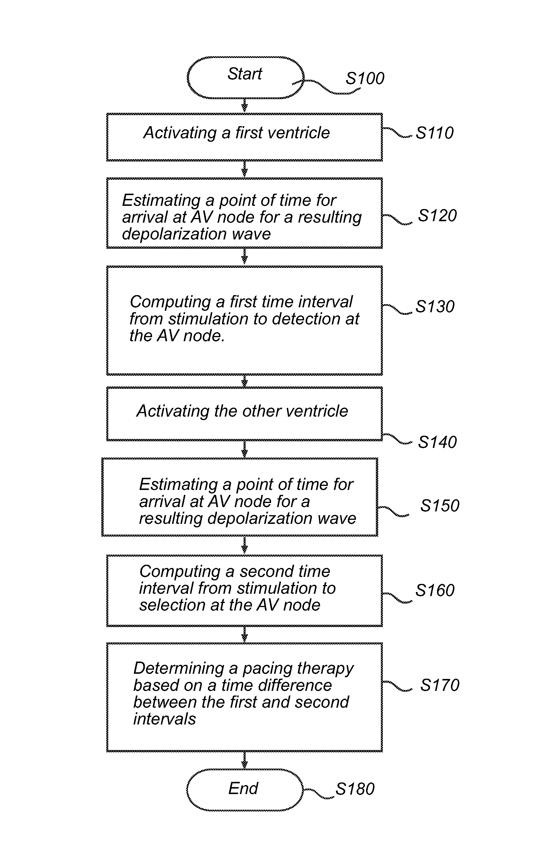
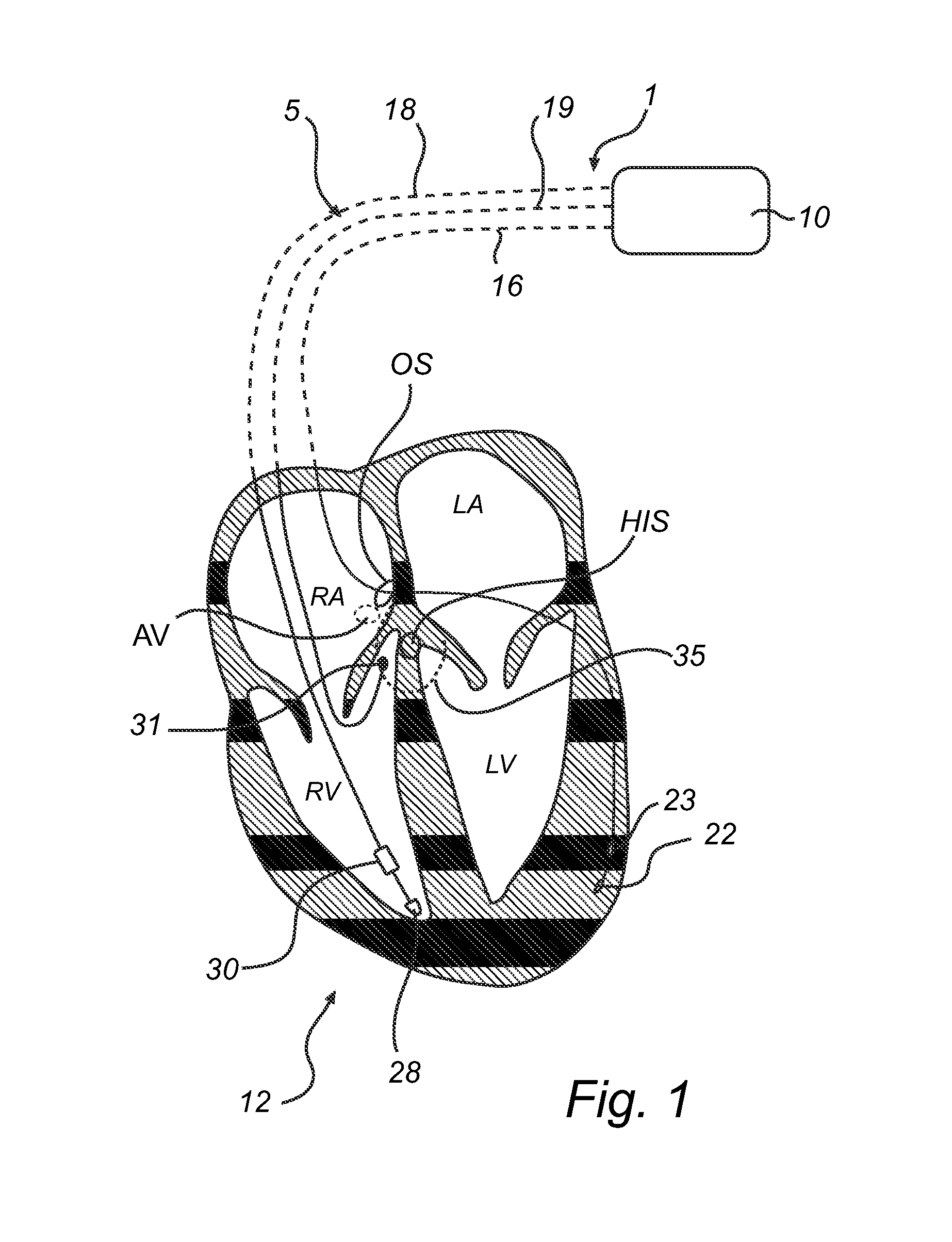
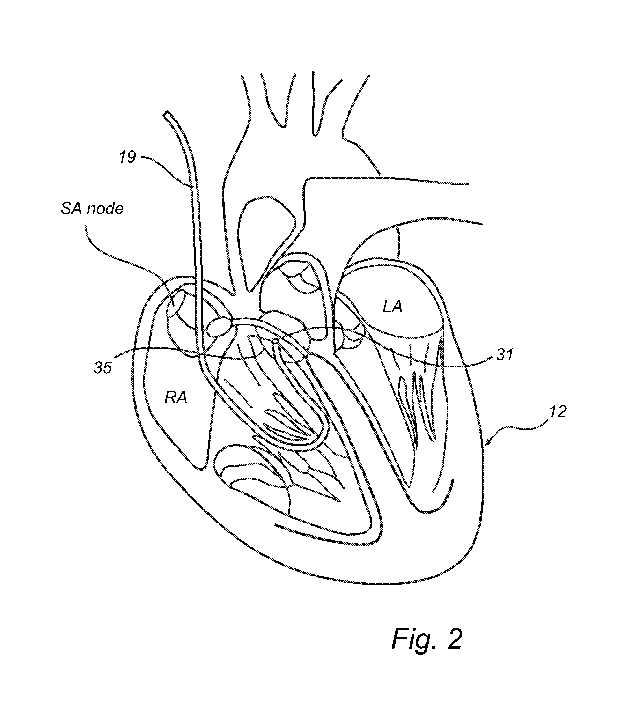
[0042]According to the present invention, the VV-delay optimization is preferably performed, generally described, by using a right ventricular tip electrode (or a right ventricular ring electrode) and the left ventricular tip electrode (or a left ventricular ring electrode) for delivering stimulation pulses and by using an electrode placed in close vicinity to HIS bundle, in close vicinity to the orifice of the Coronary Sinus or in left or right atrium for detecting the resulting depolarization wave as will be described below with reference to FIG. 1-4.

[0043]Referring fi...


PUM


Abstract

A first ventricle is stimulated at a stimulation site, a point of time for arrival at the AV node for at least one depolarization wave resulting from the stimulation is estimated and a first activation time interval substantially corresponding to the time interval required for at least one depolarization wave to travel from the stimulation site in the first ventricle to the AV node is computed. A similar process is used to compute a second activation time interval for the other ventricle. Based on these activation time intervals and a difference between the intervals, a pacing therapy can be determined.

Description

FIELD OF THE INVENTION[0001]The present invention relates generally to implantable medical devices and more particularly to systems and methods for stimulating a heart of a patient.BACKGROUND OF THE INVENTION[0002]Cardiac resynchronization therapy (CRT) has been proven to be a good method to help patients with congested heart failure and bundle branch block. The optimal ventricular stimulation delay (VV-delay) is often selected by use of echocardiography or invasive LV dP / dt (max) measurements.[0003]When using echocardiography, lateral movements of the interventricular septum indicate a suboptimal VV-delay. When the biventricular stimulation is performed with an optimal VV-delay, the septal movements laterally are minimized. Thus, if the propagation times from the right and left ventricles to the AV node in the septum is different, this can be compensated by a programmed VV-delay that ensures simultaneous arrival of the action potential to the septum.[0004]Measuring left ventricular...

Claims


Application Information

Patent Timeline
Patent Type & Authority Patents(United States)
IPC IPC(8): A61N1/368A61N1/362
CPCA61N1/368A61N1/3622A61N1/3682A61N1/3684A61N1/36843
Inventor HEDBERG, SVEN-ERIKHOLMSTROM, NILSJARVERUD, KARIN
Owner ST JUDE MEDICAL
Why Eureka
Try Eureka