Measuring stereoscopic quality in a three-dimensional computer-generated scene

Active Publication Date: 2015-10-20
DREAMWORKS ANIMATION LLC
View PDF20 Cites 8 Cited by
  • Summary
  • Abstract
  • Description
  • Claims
  • Application Information

AI Technical Summary

Benefits of technology

[0010]In one exemplary embodiment the stereoscopic quality of a computer-generated object in a three-dimensional computer-generated scene is determined. The computer-generated object is visible from at least one camera of a pair of cameras used for creating a stereoscopic view of the computer-generated scene. A set of surface vertices of the computer-generated object is obtained. A stereoscopic transformation on the set of surface vertices is computed to obtain a set of transformed vertices. The set of transformed vertices are representative of a stereoscopic shape distortion of the computer-generated object. A translation vec

Problems solved by technology

One drawback to stereoscopic films is that the shape of computer-generated objects may appear distorted to a viewer sitting in a theater.
The computer-

Method used


Image

  • Measuring stereoscopic quality in a three-dimensional computer-generated scene
  • Measuring stereoscopic quality in a three-dimensional computer-generated scene
  • Measuring stereoscopic quality in a three-dimensional computer-generated scene

Examples


Embodiment Construction

[0023]The following description is presented to enable a person of ordinary skill in the art to make and use the various embodiments. Descriptions of specific devices, techniques, and applications are provided only as examples. Various modifications to the examples described herein will be readily apparent to those of ordinary skill in the art, and the general principles defined herein may be applied to other examples and applications without departing from the spirit and scope of the various embodiments. Thus, the various embodiments are not intended to be limited to the examples described herein and shown, but are to be accorded the scope consistent with the claims.

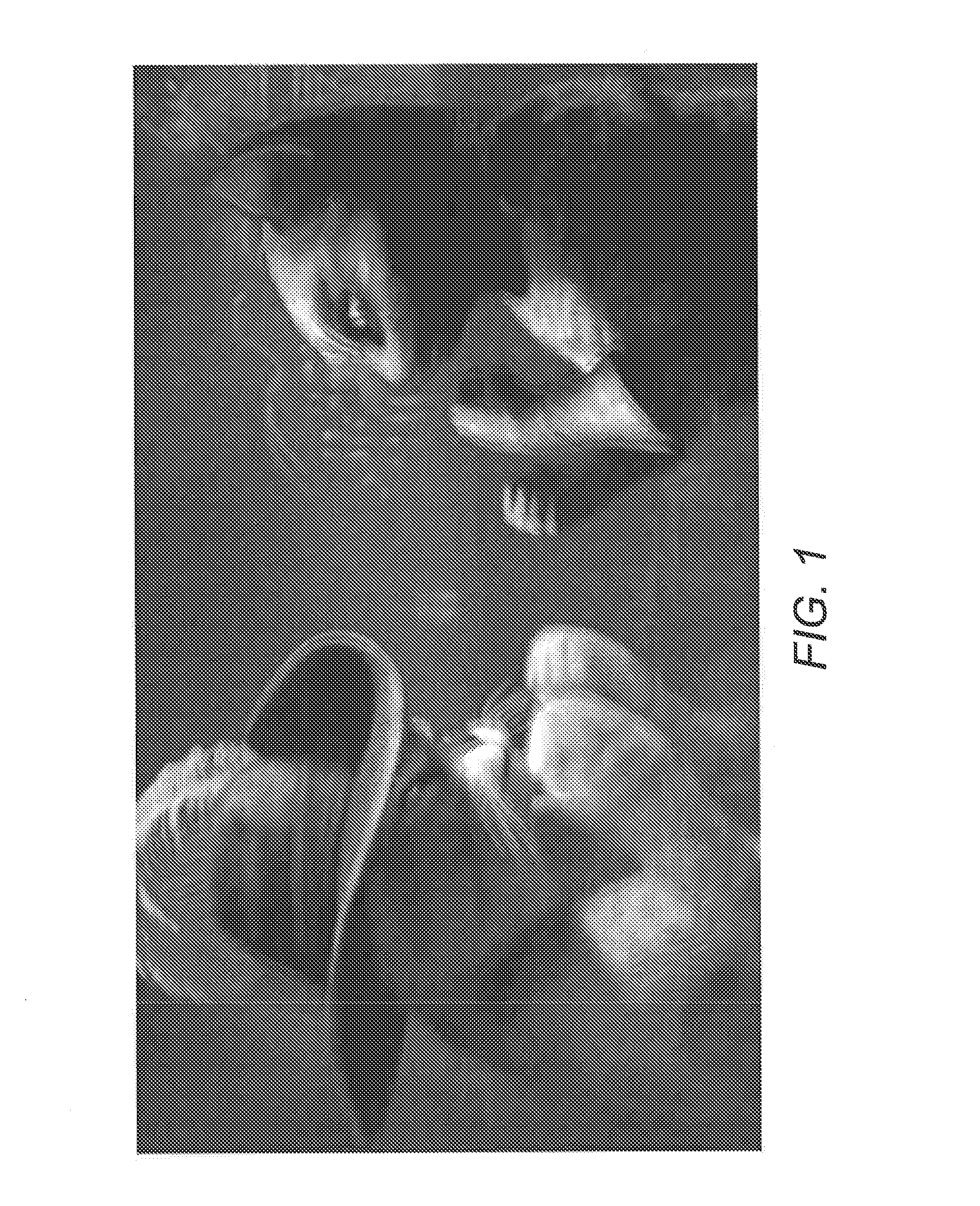
[0024]FIG. 1 depicts a stereoscopically filmed, computer-generated scene. The scene depicts two animated characters viewed in profile from the side. For purposes of this discussion, each animated character is treated as a single computer-generated object. The image depicted in FIG. 1 is a composite of two views of the c...


PUM


Description

BACKGROUND[0001]1. Field[0002]The present disclosure relates generally to measuring stereoscopic quality, and more specifically to determining a quantitative measurement of perceived distortion in a computer-generated object depicted in a stereoscopic computer-generated scene.[0003]2. Related Art[0004]Cinematographic-quality computer animation has evolved to produce increasingly realistic and engaging visual effects. One way that this is accomplished is through the use of stereoscopic filming techniques that simulate human binocular vision by presenting slightly different viewpoints of a scene to a viewer's left and right eye. This technique, also known colloquially as “3D,” can be used to enhance the illusion of depth perception and make objects in a computer-generated scene appear to extend outward from a two-dimensional screen.[0005]In normal human binocular vision, each eye views the world from a slightly different perspective. The difference in the view from each eye, also call...

Claims


Application Information

Patent Timeline
IPC IPC(8): G06T15/00G06K9/00H04N13/00H04N13/04H04N13/02G06T7/00
CPCG06T15/00H04N2013/0074H04N13/0246G06T7/002H04N17/00H04N13/246
Inventor LOW, MATTHEWGREENBERG, DONALDMCNALLY, PHILIP
Owner DREAMWORKS ANIMATION LLC
Why Eureka
Try Eureka