Antenna sheath

a technology of an antenna and a sheath, which is applied in the direction of pivotable antennas, antenna details, antennas, etc., can solve the problems of insertion pin loss before being assembled, device cannot meet actual operation needs, and assembly is more time-consuming and labor-intensive, so as to save assembly time and labor. , the effect of small angle adjustmen

Active Publication Date: 2015-10-20
GRAND TEK TECH
View PDF4 Cites 1 Cited by
  • Summary
  • Abstract
  • Description
  • Claims
  • Application Information

AI Technical Summary

Benefits of technology

[0008]The present invention is to provide an antenna sheath, in which a tubular member is formed with a shaft hole having at least a first convex tooth, and a connector of a base unit is installed with a rotation shaft having second convex teeth, so the angle adjustment of the antenna is provided with a small angle fine tuning effect, and an insertion pin is not additionally required thereby having the advantage of saving time and labor in assembly.
[0009]The present invention is to provide an antenna sheath, in which a tubular member is additionally formed with positioning ribs and a connector is additionally formed with positioning grooves, thereby enabling the angle adjustment of the antenna to be provided with a large angle adjustment effect (0 degree, 45 degrees and any other degree between 90 to 135 degrees).
[0012]In comparison with related art, the present invention has advantageous features as follows: an insertion pin is not required additionally, thereby achieving the effects of saving time and labor in assembly and an concern of losing the insertion pin is avoided; moreover, not only the large angle adjustment is provided, the small angle adjustment is also be provided.

Problems solved by technology

However, the existing angle adjustment device can only provide the adjustment for several large angles, a small angle adjustment is unable to be carried out, thus the mentioned device can not satisfy the actual operation needs.
Moreover, the existing antenna sheath has to be additionally provided with an insertion pin inserted between the tubular member and the base unit, so the angle adjustment can be processed with the insertion pin serving as the shaft, thereby causing the assembly to be more time consuming and labor consuming and causing a problem of the insertion pin may be lost before being assembled.

Method used


Image

  • Antenna sheath
  • Antenna sheath
  • Antenna sheath

Examples


Embodiment Construction

[0020]Preferred embodiments of the present invention will be described with reference to the drawings.

[0021]Please refer to FIG. 4, the present invention provides an antenna sheath, which is used in an electronic device 500 thereby allowing an antenna body (not shown in figures) of the electronic device 500 to be accommodated inside the antenna sheath for emitting or receiving wireless signals.

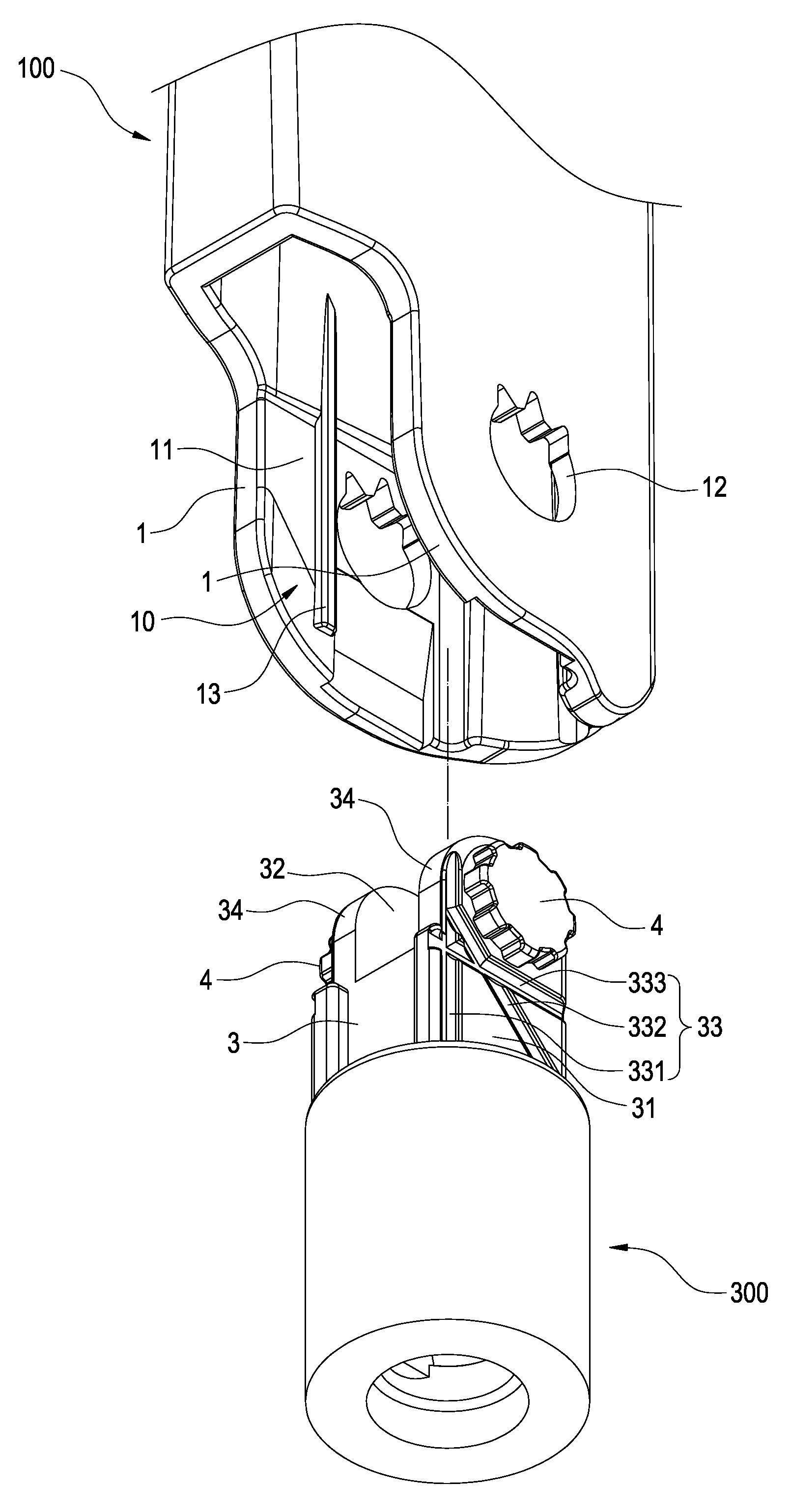
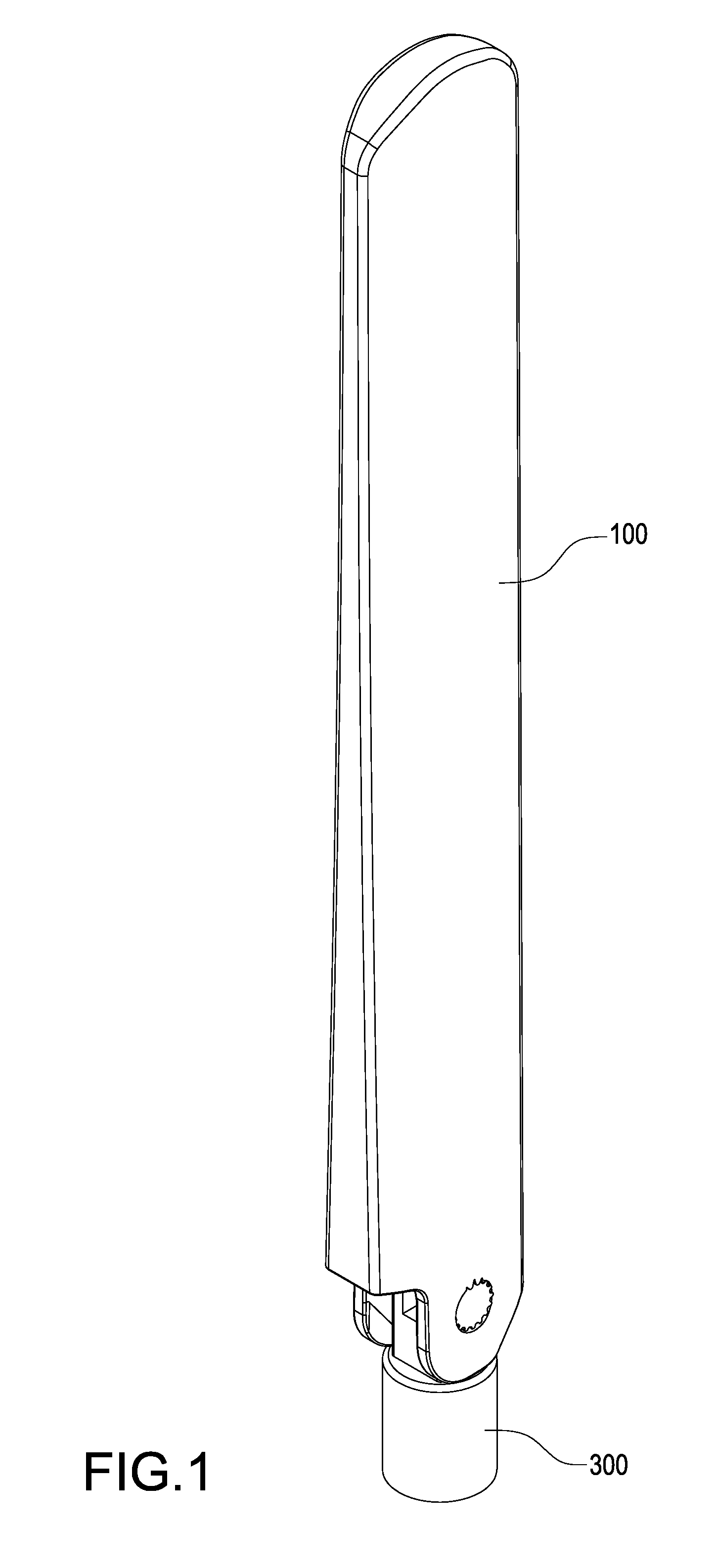
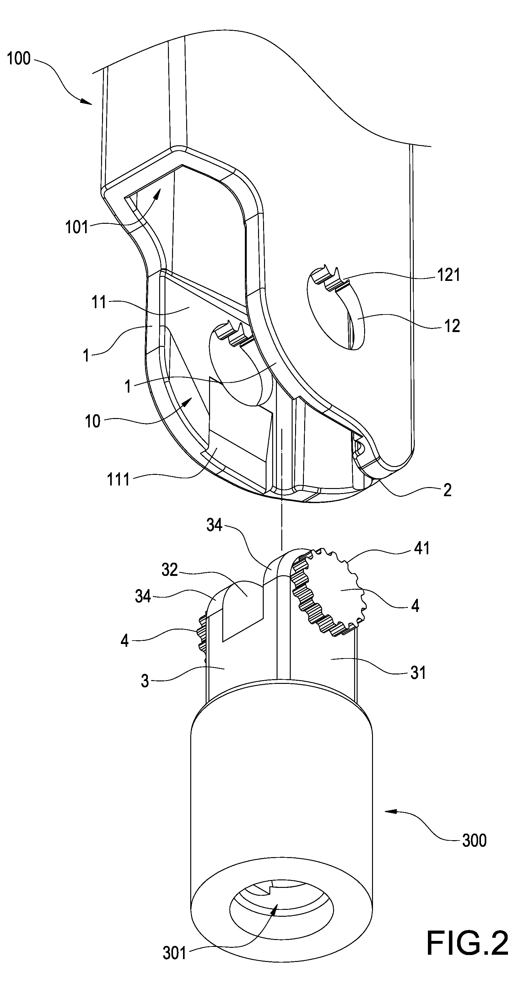
[0022]Please refer from FIG. 1 to FIG. 3, Wherein FIG. 1 is a perspective view showing the appearance of the antenna sheath according to the present invention; FIG. 2 is a partially enlarged perspective exploded view showing the antenna sheath according to the present invention; and FIG. 3 is a partially enlarged perspective view showing the assembly of the antenna sheath according to the present invention. According to the present invention, the antenna sheath includes a tubular member 100 and a base unit 300.

[0023]The tubular member 100 is formed as a hollow tube, and formed with a first cha...


PUM


Abstract

An antenna sheath includes a tubular member and a base unit. One end of the tubular member is formed with two lateral boards corresponding to each other, an opening is formed between the two lateral boards, each of the lateral boards is formed with a shaft hole, and the inner periphery of at least one of the two shaft holes is formed with at least one first convex tooth; the base unit is installed with a connector inserted in the opening and formed with two lateral surfaces corresponding to each other, the two lateral surfaces are respectively installed with a rotation shaft correspondingly pivoted in the shaft hole, the outer periphery of at least one of the two rotation shafts is formed with plural second convex teeth annularly arranged, and the first convex teeth is engaged between any two of the adjacent second convex teeth.

Description

BACKGROUND OF THE INVENTION[0001]1. Field of the Invention[0002]The present invention relates to an antenna sheath, especially to an antenna sheath capable of being processed with an angle adjustment.[0003]2. Description of Related Art[0004]An antenna is mainly used for transmitting wireless signals and applied in the technical fields such as broadcasting, wireless internet or personal mobile communication. An antenna includes an antenna sheathe and an antenna body accommodated inside the antenna sheath, for the purpose of facilitating the antenna emitting and receiving wireless signals, the antenna sheath is designed to have its inclined angle being adjustable.[0005]A conventional antenna sheath includes a tubular member, a base unit and an insertion pin. The base unit is installed with a connector which is inserted in the bottom end of the tubular member, and the insertion pin is radially inserted therebetween thereby forming a pivotal connecting status. Wherein, the angle adjustm...

Claims


Application Information

Patent Timeline
Patent Type & Authority Patents(United States)
IPC IPC(8): H01Q1/42H01Q1/08H01Q3/04
CPCH01Q3/04H01Q1/084H01Q1/42H01Q1/428
Inventor LIN, YU-WEI
Owner GRAND TEK TECH
Why Eureka
Try Eureka