Refining plate attached to a head in a pulp refiner

a pulp refiner and refining plate technology, applied in cocoa, food science, application, etc., can solve the problems of significant increase in refining surface, increase the cost of refining plate, and reduce the time to install and/or replace plates.

Active Publication Date: 2008-04-01
OVIVO LUXEMBOURG R L
View PDF14 Cites 0 Cited by
  • Summary
  • Abstract
  • Description
  • Claims
  • Application Information

AI Technical Summary

Benefits of technology

[0004]The fasteners are located outside the refining area of the plates, resulting in a significant increase in refining surface. Since there is only two fasteners per plate, the time to install and / or replace plates is significantly reduced. The plates are manufactured to tight tolerances, so that when a set of plates is installed, each plate is angled into position without requiring any radial movement. This helps to insure that minimal gap occur between the plates. The tight tolerances increase the cost of the refiner plates, but the savings realized due to fewer holes in the plates and fewer tapped holes in the heads, as well as savings in assembly and disassembly, more than offset the increased costs.

Problems solved by technology

The fasteners are located outside the refining area of the plates, resulting in a significant increase in refining surface.

Method used


Image

  • Refining plate attached to a head in a pulp refiner
  • Refining plate attached to a head in a pulp refiner
  • Refining plate attached to a head in a pulp refiner

Examples


Embodiment Construction

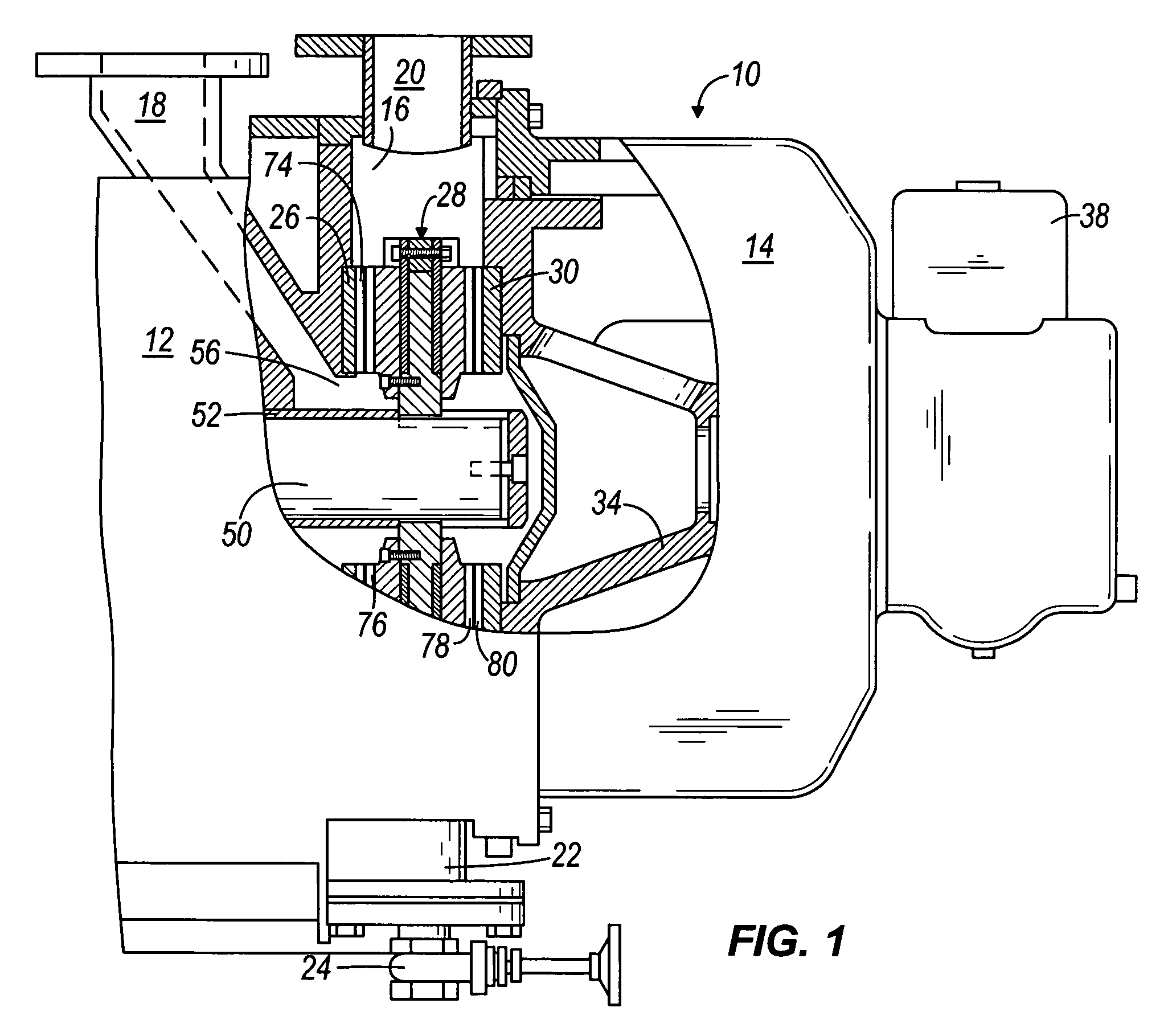
[0014]As illustrated in FIG. 1, the invention provides a disc refiner having a housing 10 including several bolted-together sections, two of which are shown at 12 and 14. The housing defines a stock chamber 16 and has an inlet 18 for admission of pulp, a first outlet 20 for evacuation of the refined pulp, at least in part under the action of centrifugal force, and a second outlet 22 that is normally closed by a suitable valve 24. The outlet 20 extends upwardly and the outlet 22 extends downwardly. The valve 24 is opened when the attendants wish to drain the liquid carrier for wood chips or the like from the chamber 16. Although a particular housing geometry is shown, no particular housing construction is required.

[0015]The chamber 16 accommodates three refining members 26, 28, and 30, here shown as coaxial discs having identical outer diameters. In other embodiments (not shown), two back-to-back discs can be used instead of the single disc 28. In still other embodiments (not shown),...


PUM

PropertyMeasurementUnit
axial rotationaaaaaaaaaa
areaaaaaaaaaaa
diameteraaaaaaaaaa

Abstract

A refiner plate has an outer circumferential edge, a front surface having comminuting projections, and a rear surface. The refiner plate also has and a single mounting opening radially inward from the outer circumferential edge. The refiner plate also includes a radially extending key attached to the rear surface, the key having an end forming a tab that extends past the plate outer circumferential edge.

Description

BACKGROUND OF THE INVENTION[0001]This invention is directed to pulp refiners, and, more particularly, to the mechanism used for attaching a refining plate to its supporting head.[0002]Some refiners for wood pulp or the like, have stationary refining plates that flank rotary refining plates in the chamber of a housing whose inlet admits stock for treatment by comminuting projections (e.g., ribs) on the neighboring surfaces of stationary refining plates and rotary refining plates. Currently, the set of refining plates that are mounted to the rotating and stationary heads use four or more fasteners for each refiner plate. Mounting holes are normally located in the refining area of the plates, thus reducing the useful refining surface. The plates fit against an outer ring at the outside diameter of the head. The outer ring contains the plates in proper location and prevents outward movement due to centrifugal forces. The fasteners are designed to carry all the torsional forces acting on...

Claims


Application Information

Patent Timeline
Patent Type & Authority Patents(United States)
IPC IPC(8): B02C7/12
CPCB02C7/12D21D1/306
Inventor TEMPESTA, NAZARENO T.SKILLING, GILLES P.ALBERT, KENT P.
Owner OVIVO LUXEMBOURG R L
Why Eureka
Try Eureka