Device for pushing glass objects onto a conveyor belt

Active Publication Date: 2014-01-21
HEYE INT
View PDF14 Cites 2 Cited by
  • Summary
  • Abstract
  • Description
  • Claims
  • Application Information

AI Technical Summary

Benefits of technology

[0013]Further protection of the device against the effects of heat, moisture, abrasive dust, etc. is achieved by the housing being disposed below the plane of a dead plate.
[0014]The mechanical concept of the device, unlike in the Prior Art illustr

Problems solved by technology

The transfer of the rotational movements of the three drives via the levers to the pusher is effected

Method used


Image

  • Device for pushing glass objects onto a conveyor belt
  • Device for pushing glass objects onto a conveyor belt
  • Device for pushing glass objects onto a conveyor belt

Examples


Embodiment Construction

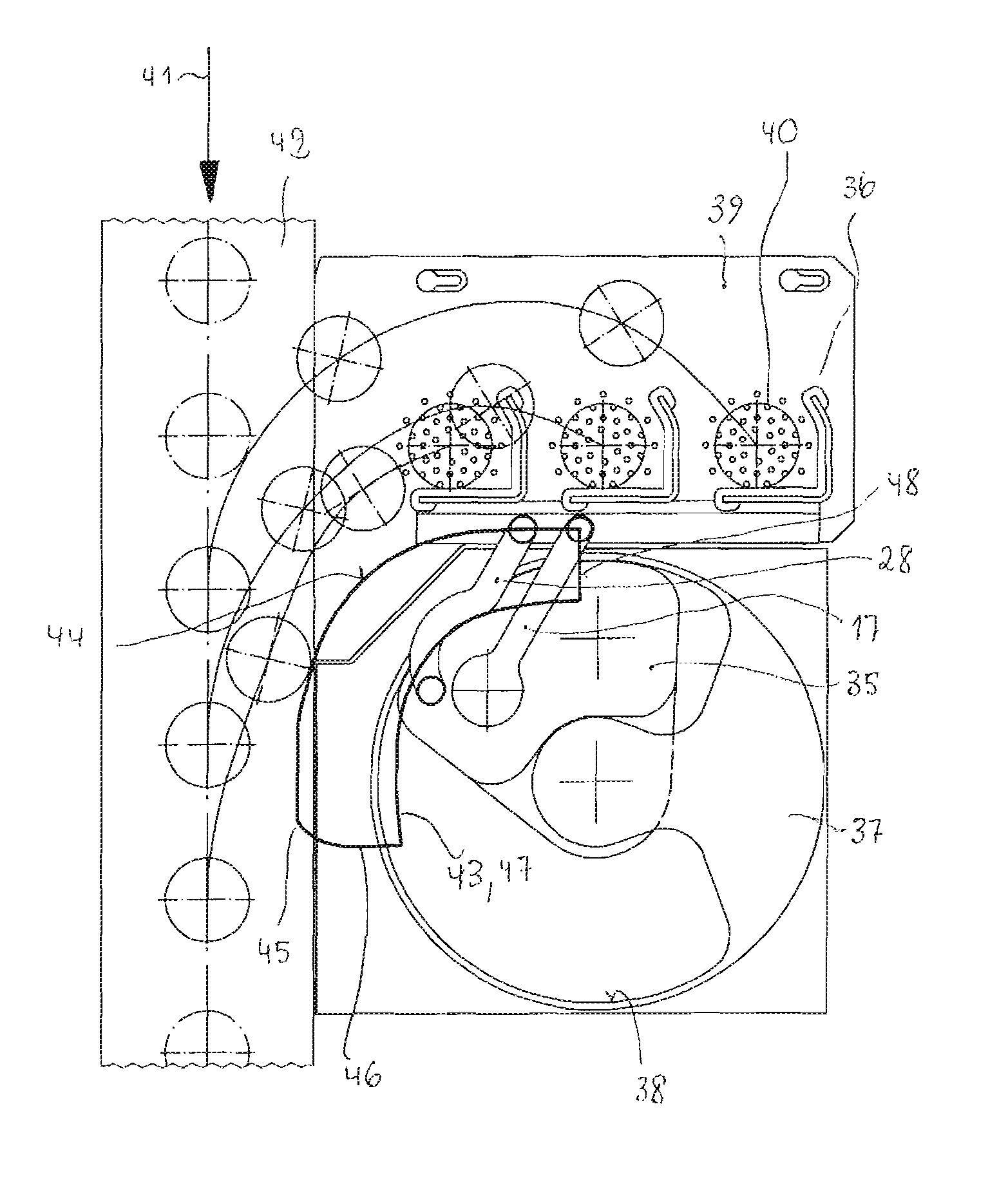
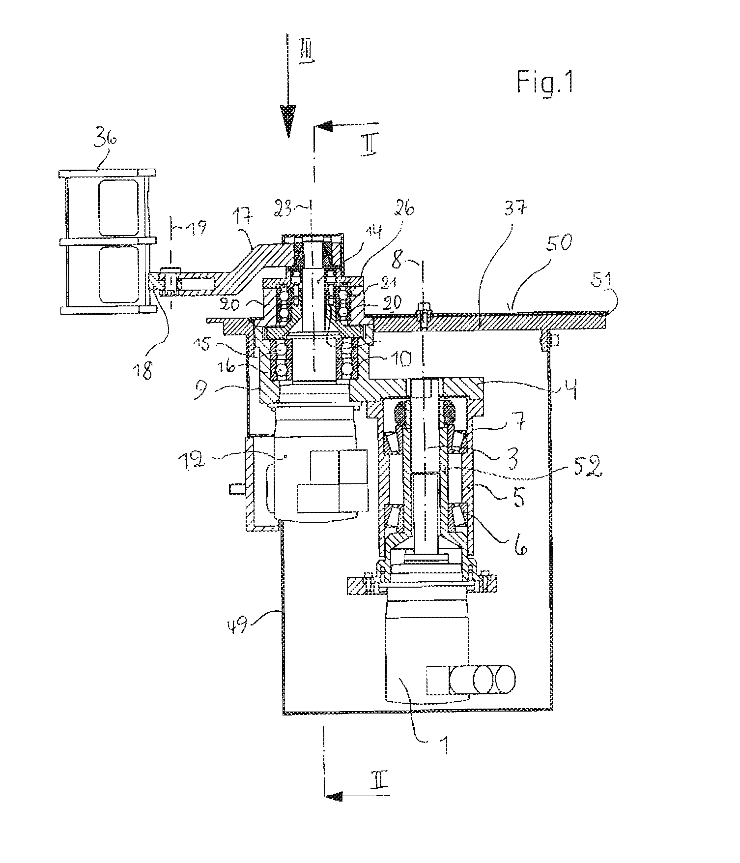
[0020]Reference numeral 1 designates a first electric motor disposed in a frame 2 in a positionally-fixed manner, the driven shaft 3 of which is connected to a beam 4 in a rotationally-fixed manner. The driven shaft 3 extends through a hollow shaft-like hub 52 and the beam 4 is connected to a hollow cylinder 5 surrounding the hub 52, the beam being mounted on the hub 52 via the hollow cylinder by means of roller bearings 6, 7.

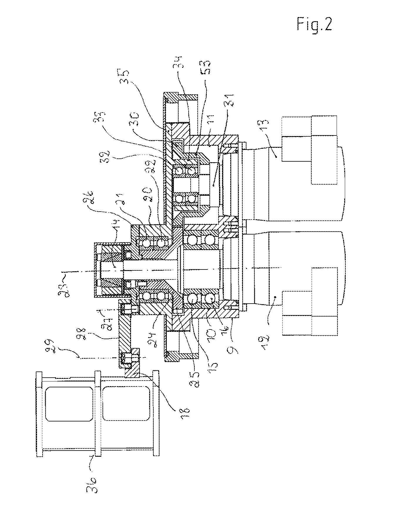
[0021]The beam 4 which is thus mounted so as to be rotatable about a vertical, positionally-fixed axis 8 supports at its end remote from the axis 8 a receiving body 9 which, as shown in FIG. 2, comprises two cylindrical receptacles 10, 11 which are disposed next to each other and whose axes extend in parallel with the axis 8.

[0022]A second electric motor 12 is inserted into the lower portion of the receptacle 10 and a third electric motor 13 is inserted into the lower portion of the receptacle 11.

[0023]The shaft 14 mounted within the receptacle 10 via roller be...


PUM

PropertyMeasurementUnit
Speedaaaaaaaaaa
Dimensionaaaaaaaaaa

Abstract

A device having a pusher for pushing glass objects from a resting plate to a conveyor belt moving at a uniform speed. The device has first, second and third electric motors, the first motor mounted to be stationary, and the second and third motors being moveable relative to the first motor. The three motors are connected to the pusher via various transmission parts and controlled independently for controlling the motion of the pusher.

Description

BACKGROUND OF THE INVENTION[0001]The invention relates to a device for pushing glass objects from a dead plate of an I.S. glassware forming machine onto a conveyor belt.[0002]Such devices are intended to transfer the glass object, in particular a hollow glass object, which has been removed from a blow-mold of a glassware forming machine and placed on a stationary dead plate. The device then transfers the glass object by means of a pusher to a conveyor belt moving continuously at a uniform speed. The glass objects must be positioned on the conveyor belt one behind the other to be subsequently introduced into a lehr. In the case of I.S. (individual section) machines where the conveyor belt co-operates with a plurality of manufacturing stations, each of which is provided with a dead plate, the process of pushing the glass objects must take place within a time interval dependent upon the operating cycle of the remaining manufacturing stations and upon the transport speed of the belt. Mo...

Claims


Application Information

Patent Timeline
IPC IPC(8): B65G47/34
CPCC03B9/453B65G47/04
Inventor FELGENHAUER, BENEDIKTHUBNER, MATTHIAS
Owner HEYE INT
Why Eureka
Try Eureka