
Truck rear lamp

a rear lamp and truck technology, applied in the direction of vehicle components, signalling/lighting devices, optical signalling, etc., can solve the problems of high production cost, troublesome assembly of vehicle lights, etc., and achieve the effect of reducing production cost and saving time and labor in assembly

Inactive Publication Date: 2011-01-13
LUCIDITY ENTERPRISE
View PDF5 Cites 9 Cited by
  • Summary
  • Abstract
  • Description
  • Claims
  • Application Information

AI Technical Summary

Benefits of technology

"The invention is a truck rear lamp that includes a housing with a circuit board and LEDs for different purposes of lighting and warning. The lamp has a main lamp shell, side lamp shell, and license-plate lamp shell combined together. The housing has a main accommodating chamber with a side lamp seat and a side accommodating chamber with a side through hole communicating with the main chamber. The circuit board has plural main LEDs and a reflecting mirror positioned at one side of the license plate LEDs. The main lamp shell is assembled on the front side of the housing, the side lamp shell is positioned on the side lamp seat, and the license-plate lamp shell is mounted on the large hole of the bottom side of the housing. The invention saves time and labor in assembly and reduces producing cost."

Problems solved by technology

In other words, LEDs with different uses have to be respectively installed on three printed circuit boards that are to be respectively assembled at a location in a first light shell and in a second light shell for attaining different purposes of warning, thus troublesome in producing and assembling the components of vehicle lights and high in producing cost.

Method used


Image

  • Truck rear lamp
  • Truck rear lamp
  • Truck rear lamp

Examples


Embodiment Construction

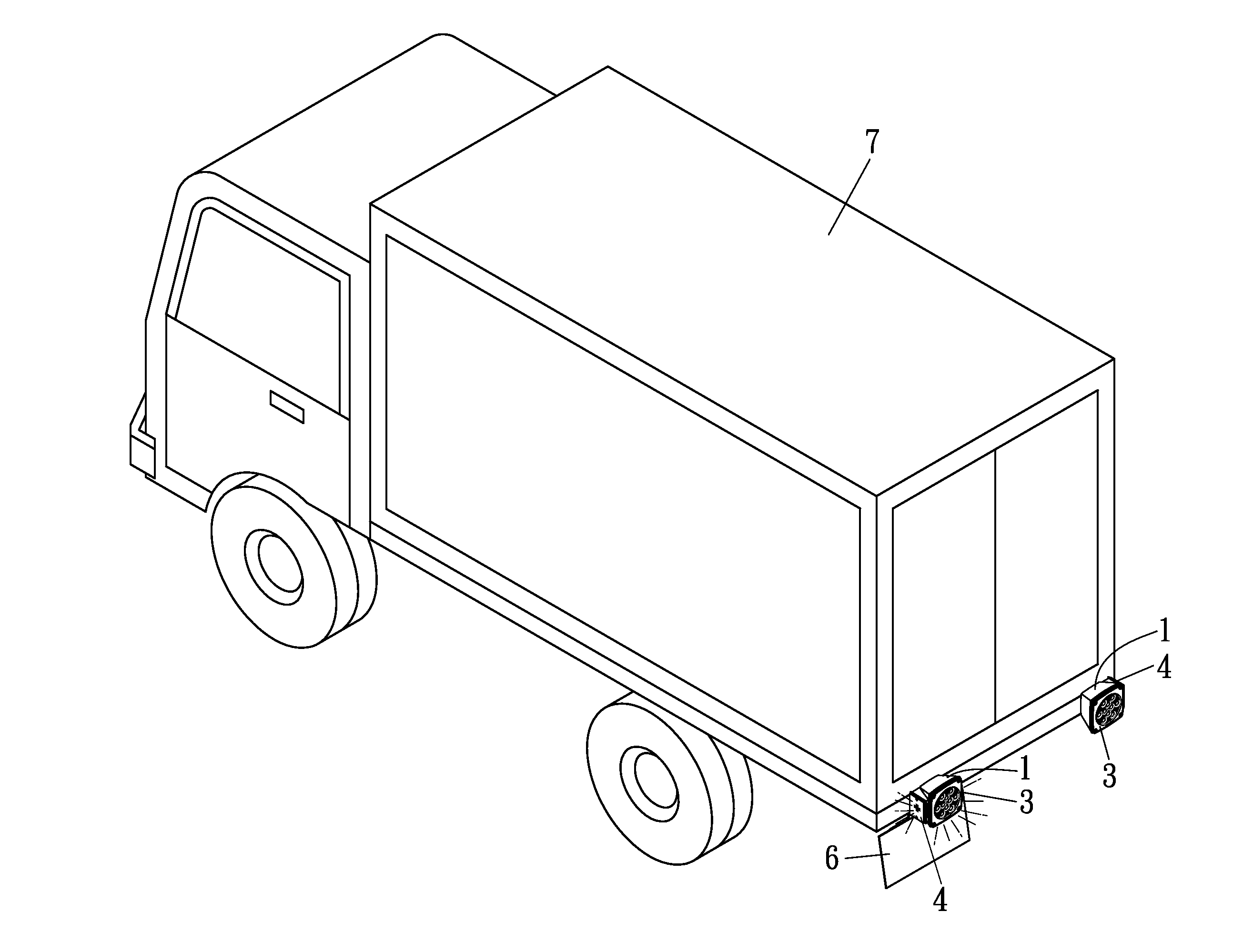
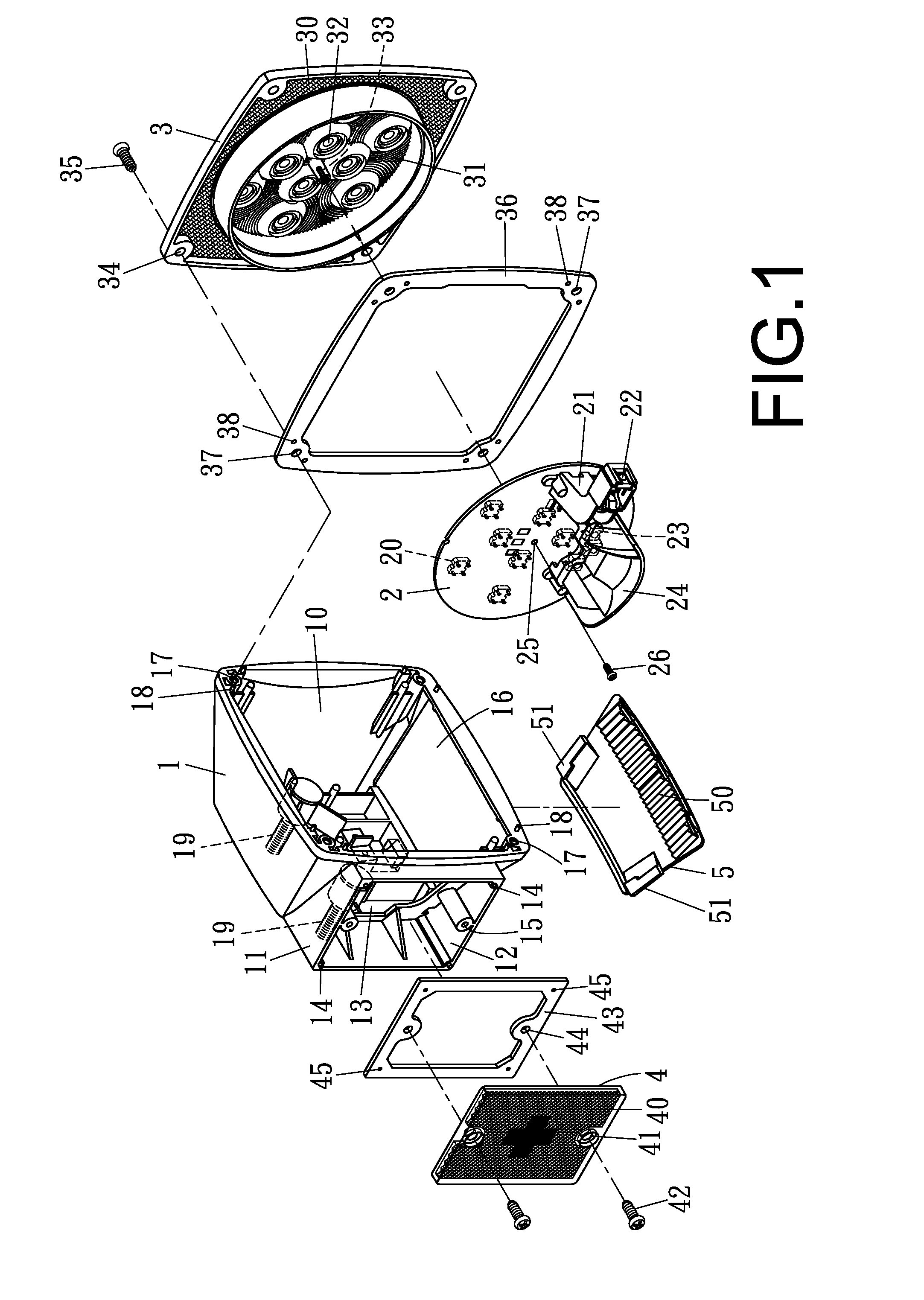
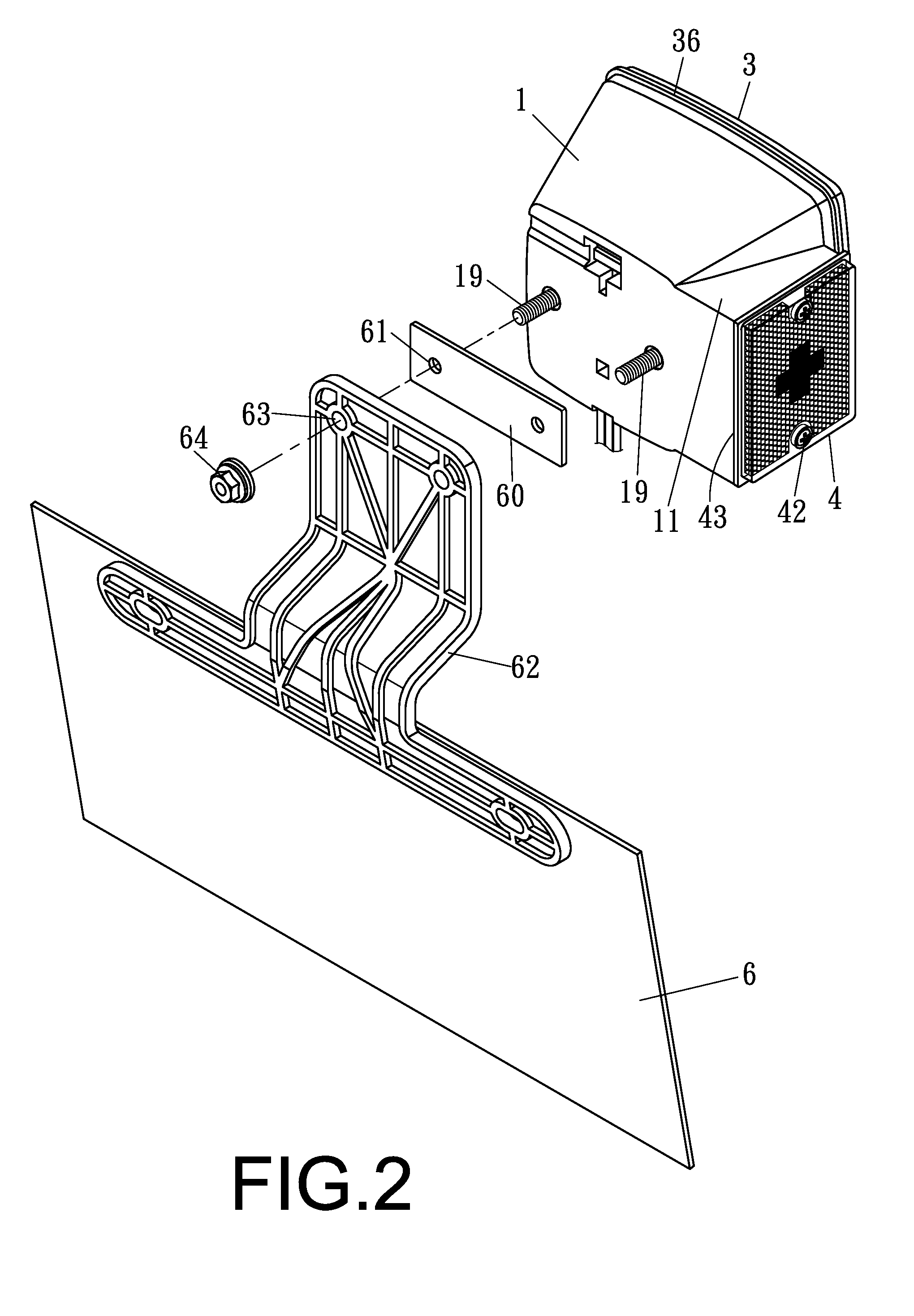
[0019]A preferred embodiment of a truck rear lamp in the present invention, as shown in FIGS. 1, 2, 4 and 5, includes a base 1, a unitary circuit board 2, a main lamp shell 3, a side lamp shell 4 and a license-plate lamp shell 5 combined together.

[0020]The housing 1 is provided with a main accommodating chamber 10 in the interior and has one sidewall formed integral with a side lamp seat 11 having a side accommodating chamber 12 and bored inside with a side through hole 13 communicating with the main accommodating chamber 10. The side lamp seat 11 further has four corners respectively fixed thereon with a positioning stud 14 and two sides respectively and oppositely bored with a threaded hole 15. In addition, the housing 1 is formed with a large hole 16 at the bottom side, having four corners of an open front side respectively bored with a threaded hole 17 and two positioning studs 18 and also having a rear sidewall secured with two threaded bolts 19.

[0021]The circuit board 2 to be ...


PUM


Abstract

A truck rear lamp includes a housing, a unitary circuit board, a main lamp shell, a side lamp shell and a license-plate lamp shell combined together. The circuit board has a front side provided with plural main LEDs and a rear side fixed with a connecting seat having an outer end disposed with a side LED, further having plural license plate LEDs arranged at a location near the bottom of a rear side, and the license plate LEDs has one side provided with a reflecting mirror. The unitary circuit board received in the housing is installed thereon with LEDs respectively located at different locations for carrying out different-purpose lighting and warning, able to save time and labor in assembly and lower producing cost.

Description

BACKGROUND OF THE INVENTION[0001]1. Field of the Invention[0002]This invention relates to a truck rear lamp, particularly to one having a base provided therein with a unitary circuit board disposed thereon with LEDs respectively located at different regions for carrying out different purposes of lighting and warning, able to save time and labor in assembly and lower producing cost.[0003]2. Description of the Prior Art[0004]A first conventional truck rear lamp, as disclosed in a U.S. Pat. No. 5,934,798, can only be used for illuminating the license plate of a truck, but cannot be used as a brake lamp or a side marker lamp. A second conventional truck rear lamp, as disclosed in another U.S. Pat. No. 6,533,445 B1, titled “VEHICLE LIGHT”, is to have light source (LEDs) and a circuit module connected between a first light shell and a second light shell. The first array of LEDs on the circuit module are arranged side by side and aimed at a tail light shell and connected to a first printed...

Claims


Application Information

Patent Timeline
Patent Type & Authority Applications(United States)
IPC IPC(8): B60Q1/00
CPCB60Q1/2607B60Q1/56B60Q1/2696
Inventor TSAI, HSI-HSIENLEI, CHI-KANG
Owner LUCIDITY ENTERPRISE
Learn More