Leadless cardiac pacemaker with conducted communication

a pacemaker and led-less technology, applied in the field of led-less cardiac pacemakers with conducted communication, can solve the problems of subcutaneous pulse generators that can exhibit erosion, extrusion, infection, disconnection, etc., and achieve the effects of reducing the risk of cardiac arres

Active Publication Date: 2015-10-27
PACESETTER INC
View PDF557 Cites 134 Cited by
  • Summary
  • Abstract
  • Description
  • Claims
  • Application Information

AI Technical Summary

Benefits of technology

[0029]The leadless pacemaker can further include a controller in the hermetic housing, and the controller can be configured to communicate with the external device by transferring the information through the at least two electrodes. The controller can be configured to communicate with the external device by transferring the information through the at least two electrodes during a pacing pulse. The controller can be configured to communicate with the external device by transferring the information through the at least two electrodes outside of a refractory period or pacing pulse. The controller can be configured to communicate with the external device by transferring the information through the at least two electrodes only during an absolute refractory period. The controller can be configured to provide charge balance of the information before the end of a refractory period. The controller can be configured to transfer information to or from the external device by sending a bell-ringer signal to the external device and listening for a response from the external device only during a set time period after the bell-ringer signal. The controller can be configured to send a synchronization signal through the at least two electrodes to the external device to start transfer of a part of the information. The controller can be configured to measure a length of time between encoded information signals received by the at least two electrodes. The controller can be further configured to use the measured length of time to estimate a clock frequency of the external device and optimize the timing of the transfer of information.
[0036]The external device can further include a controller, and the controller can be configured to communicate with the leadless pacemaker by transferring the information signals to or from the leadless pacemaker. The controller can be configured to transfer the information signals during a pacing pulse. The controller can be configured to transfer the information signals outside of a refractory period or pacing pulse. The controller can be configured to transfer the information only during an absolute refractory period. The controller can be configured to measure a length of time between the information signals transferred from the leadless pacemaker. The controller can be further configured to use the measured length to estimate a clock frequency of the leadless pacemaker and optimize the timing of the transfer of information.

Problems solved by technology

Although more than five hundred thousand pacemakers are implanted annually, various well-known difficulties are present.
The pulse generator, when located subcutaneously, presents a bulge in the skin that patients can find unsightly or unpleasant.
Even without persistent twiddling, subcutaneous pulse generators can exhibit erosion, extrusion, infection, and disconnection, insulation damage, or conductor breakage at the wire leads.
Although sub-muscular or abdominal placement can address some of concerns, such placement involves a more difficult surgical procedure for implantation and adjustment, which can prolong patient recovery.
The complex connection between connectors and leads provides multiple opportunities for malfunction.
For example, failure to introduce the lead pin completely into the terminal block can prevent proper connection between the generator and electrode.
Failure to insert a screwdriver correctly through the setscrew slot, causing damage to the slot and subsequent insulation failure.
Failure to engage the screwdriver correctly in the setscrew can cause damage to the setscrew and preventing proper connection.
Failure to tighten the setscrew adequately also can prevent proper connection between the generator and electrode, however over-tightening of the setscrew can cause damage to the setscrew, terminal block, or lead pin, and prevent disconnection if necessary for maintenance.
Fluid leakage between the lead and generator connector moldings, or at the setscrew cover, can prevent proper electrical isolation.
Insulation or conductor breakage at a mechanical stress concentration point where the lead leaves the generator can also cause failure.
Inadvertent mechanical damage to the attachment of the connector molding to the generator can result in leakage or even detachment of the molding.
Inadvertent mechanical damage to the attachment of the connector molding to the lead body, or of the terminal pin to the lead conductor, can result in leakage, an open-circuit condition, or even detachment of the terminal pin and / or molding.
Repeated movement for hundreds of millions of cardiac cycles can cause lead conductor breakage or insulation damage anywhere along the lead body.
Repeated abrasion between the lead body and the generator due to lead coiling can result in insulation damage to the lead.
Friction of the lead against the clavicle and the first rib, known as subclavian crush, can result in damage to the lead.
Abrasion between the leads for hundreds of millions of cardiac cycles can cause insulation breakdown or even conductor failure.
Communication between the implanted pulse generator and external programmer uses a telemetry coil or antenna and associated circuitry in the pulse generator, adding complexity that increases the size and cost of devices.
Moreover, power consumption from the pulse generator battery for communication typically exceeds power for pacing by one or more orders of magnitude, introducing a requirement for battery power capability that can prevent selecting the most optimal battery construction for the otherwise low-power requirements of pacing.

Method used


Image

  • Leadless cardiac pacemaker with conducted communication
  • Leadless cardiac pacemaker with conducted communication
  • Leadless cardiac pacemaker with conducted communication

Examples


specific examples

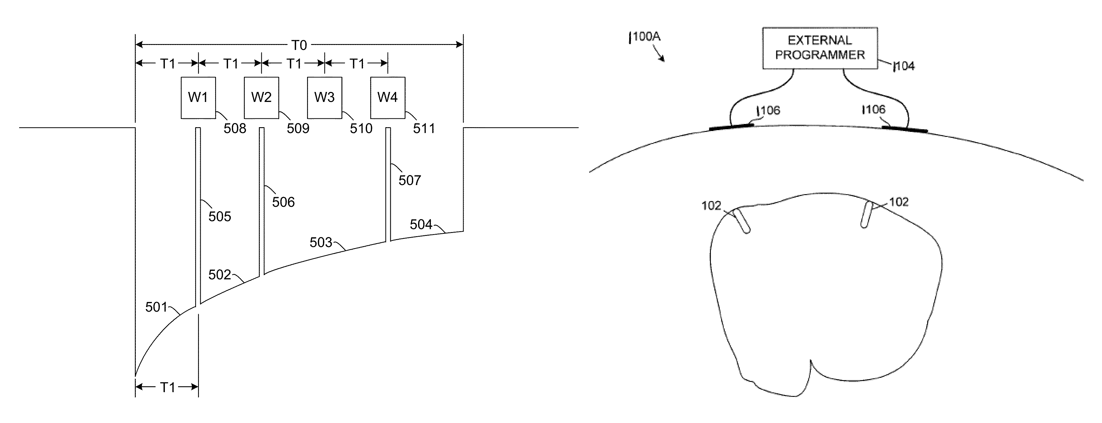
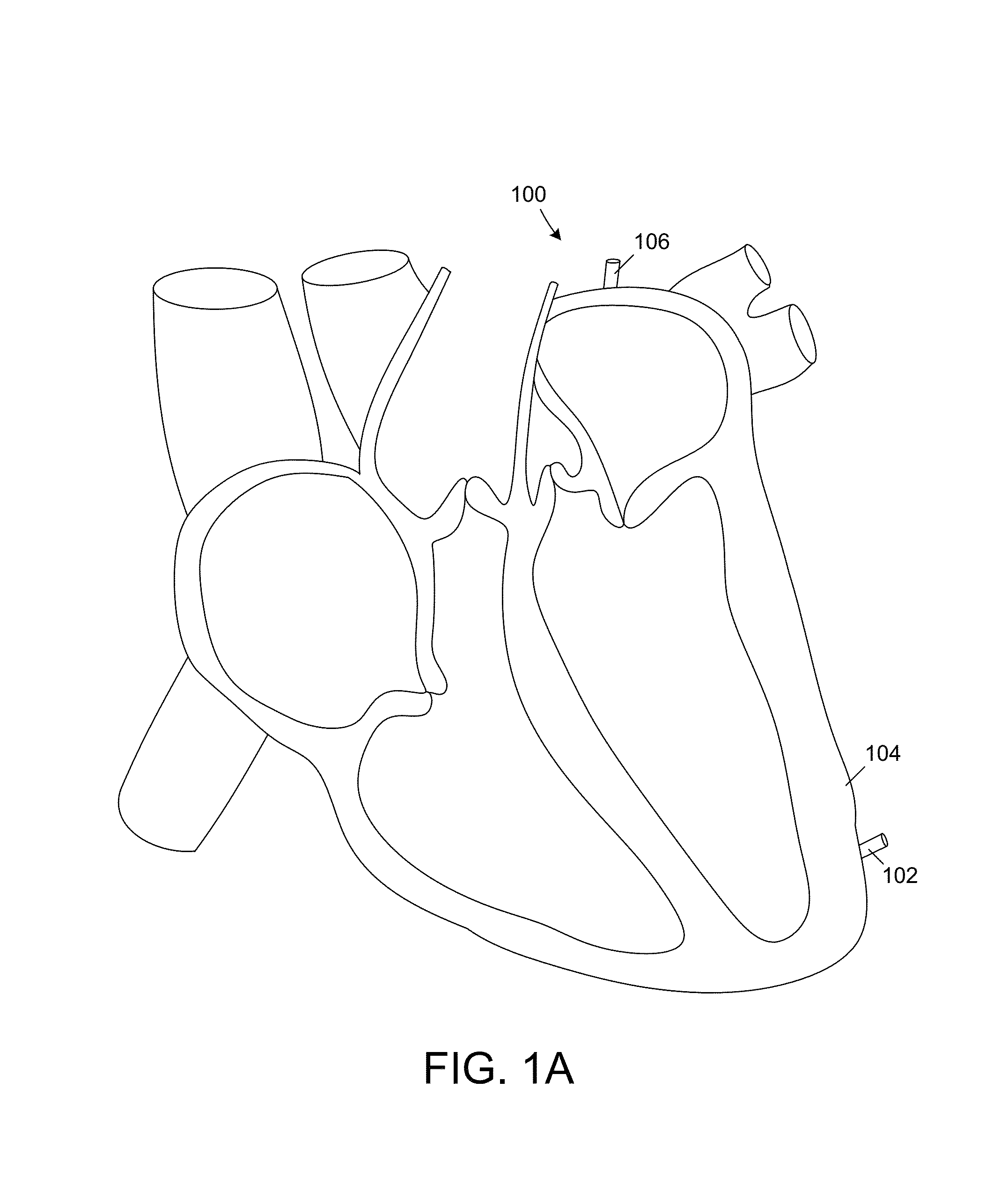
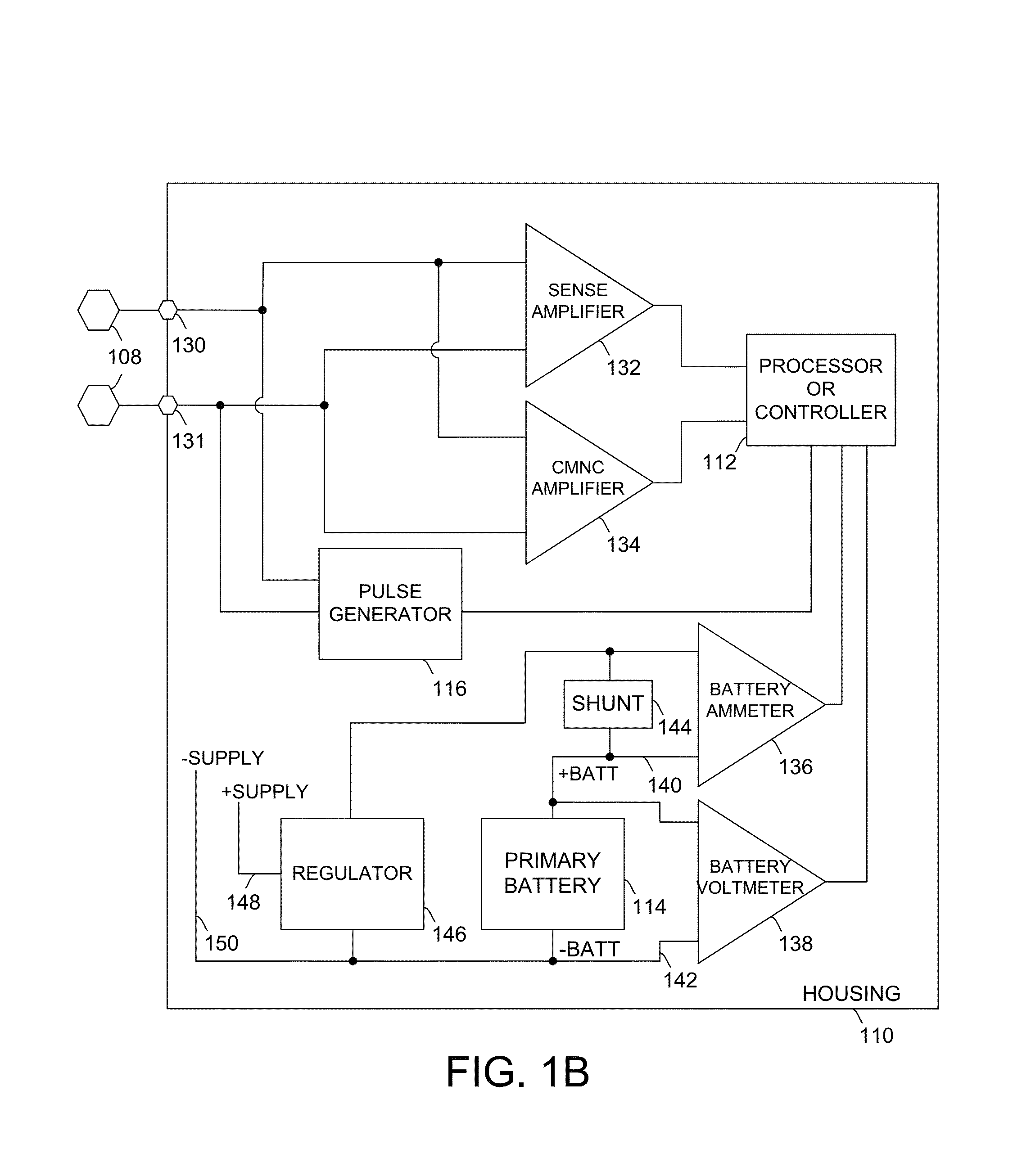
[0152]FIG. 11 illustrates one embodiment including an external programmer 106 in communication with at least one cardiac pacemakers 102, the pacemaker 102 including a first pulse generator 116 and a second pulse generator 776. The first pulse generator 116 can be used for pacing through the electrodes 108 while the second pulse generator 776 can be used for delivering communication pulses through the electrodes 108 to the external device 106. Thus, the second pulse generator 776 can be uninvolved in the pacing process. The second pulse generator 776 can generate different pulses at different amplitudes from the first pulse generator 112. Advantageously, this allows for the amplitude of the pulses to be optimized for communication or for pacing.

[0153]The second pulse generator 776 can be powered from a power supply shared with another function. This power supply can be the lowest-voltage supply already used for another function. For example, the second pulse generator 776 can use the...


PUM


Abstract

A leadless pacemaker for pacing a heart of a human includes a hermetic housing and at least two electrodes on or near the hermetic housing. The at least two electrodes are configured to deliver energy to stimulate the heart and to transfer information to or from at least one external device.

Description

CROSS REFERENCE TO RELATED APPLICATIONS[0001]This application is a continuation-in-part of U.S. application Ser. No. 13 / 109,728, entitled “PROGRAMMER FOR BIOSTIMULATOR SYSTEM”, filed May 17, 2011; which is a continuation of U.S. application Ser. No. 11 / 549,605, entitled “PROGRAMMER FOR BIOSTIMULATOR SYSTEM,” filed Oct. 13, 2006, now U.S. Pat. No. 7,945,333; which claims the benefit of priority to U.S. Provisional Application Nos. 60 / 726,706 entitled “LEADLESS CARDIAC PACEMAKER WITH CONDUCTED COMMUNICATION,” filed Oct. 14, 2005; 60 / 761,531 entitled “LEADLESS CARDIAC PACEMAKER DELIVERY SYSTEM,” filed Jan. 24, 2006; 60 / 729,671 entitled “LEADLESS CARDIAC PACEMAKER TRIGGERED BY CONDUCTED COMMUNICATION,” filed Oct. 24, 2005; 60 / 737,296 entitled “SYSTEM OF LEADLESS CARDIAC PACEMAKERS WITH CONDUCTED COMMUNICATION,” filed Nov. 16, 2005; 60 / 739,901 entitled “LEADLESS CARDIAC PACEMAKERS WITH CONDUCTED COMMUNICATION FOR USE WITH AN IMPLANTABLE CARDIOVERTER-DEFIBRILLATOR,” filed Nov. 26, 2005; 6...

Claims


Application Information

Patent Timeline
Patent Type & Authority Patents(United States)
IPC IPC(8): A61N1/00A61N1/368A61N1/372A61N1/375
CPCA61N1/3727A61N1/368A61N1/3756A61N1/37217A61N1/37288A61N1/3684A61N1/37205
Inventor JACOBSON, PETER M.OSTROFF, ALANCICIARELLI, TIMOTHY E.
Owner PACESETTER INC
Why Eureka
Try Eureka