

System and method for providing improved display quality by display adjustment and image processing using optical feedback
- Summary
- Abstract
- Description
- Claims
- Application Information
AI Technical Summary
Benefits of technology
Problems solved by technology
Method used
Image

Examples
Embodiment Construction
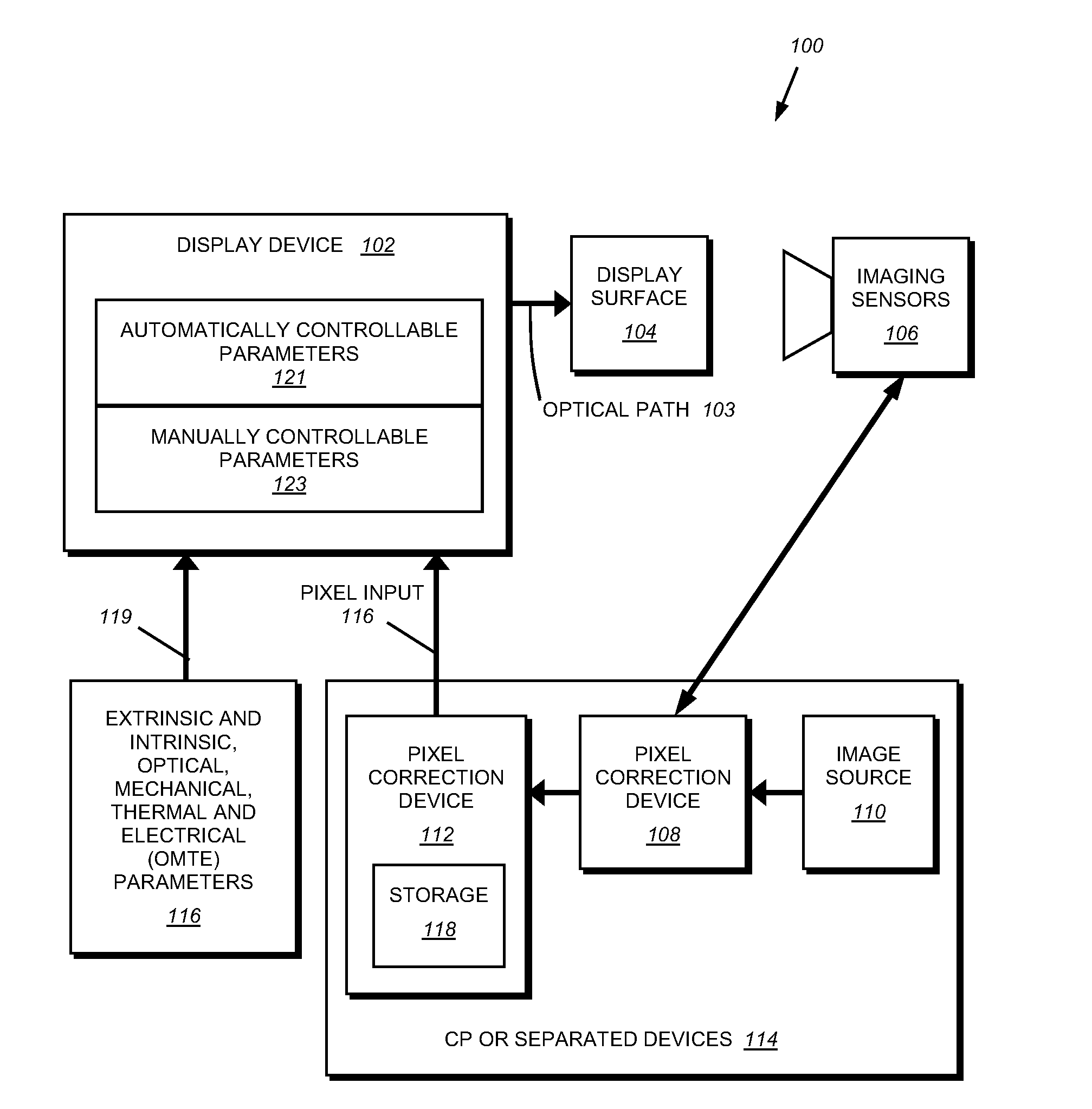
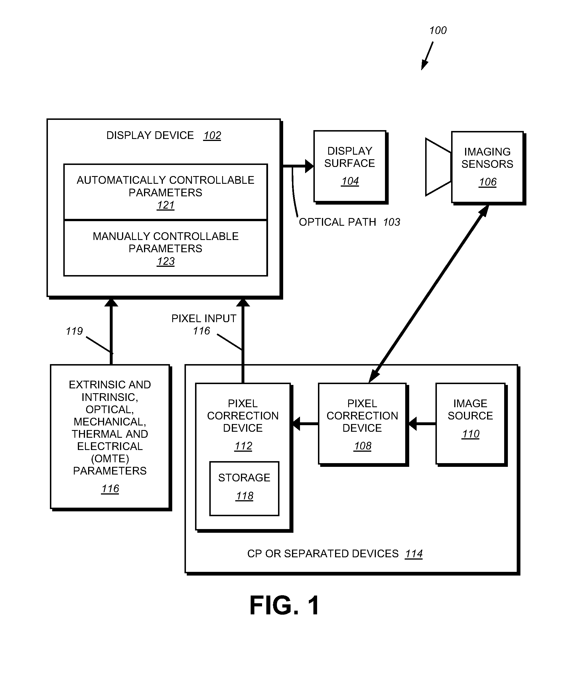
[0032]A. Sensors
[0033]By way of further background, to capture information as to the quality of the image, the system of this invention utilizes one or more light sensors. A sensor can be defined in a variety of ways and can be one of many different types, including cameras, linear arrays of light sensors, and light sensors with no inherent spatial information, such as a photo-diode. Sometimes the system requires many sensors, and sometimes it requires only one. The sensor(s) may detect infrared, ultraviolet, or visible light in either narrow or broad-wavelength bands. It / they may be sensitive to position, as an imaging camera, or insensitive to position, as a single light level sensing photodiode. Some sensors, like camera(s), may provide a sense of the three-dimensional geometry of the system.
[0034]Note that even very simple light sensors provide significant amounts of information when used in conjunction with displays / projectors, including color, intensity and spatial information...
PUM
 Abstract
Description
Claims
Application Information