
Storage box

a storage box and soleplate technology, applied in the field of storage boxes, can solve the problems of affecting the use effect, poor stability, and the inability to use foldable storage boxes, and achieve the effects of ensuring the stability of installation of the soleplate, reducing the space occupation, and reducing the cost of storage boxes

Active Publication Date: 2015-10-27
LEUNG MING FUK
View PDF21 Cites 2 Cited by
  • Summary
  • Abstract
  • Description
  • Claims
  • Application Information

AI Technical Summary

Benefits of technology

The present invention provides a storage box that can be conveniently folded for storage and remains stable when unfolded for use. The box has thin, flexible handles that can resist bending and deformation. The soleplate and lug plate are securely fixed inside the box, ensuring stability and preventing displacement or turnover. The storage box is easy to install and has improved structure stability. Overall, the present invention has improved practicality and convenience.

Problems solved by technology

Although the storage boxes, made of hard material, have firm structure and also convenience in storage of articles, they may occupy a large space during the transportation or when not in use as they cannot be folded for storage; and, although the storage boxes, made of soft material, can be folded for storage, they have a disadvantage of poor stability.
However, when such foldable storage box is placed in an uneven place or a rugged place, the side plates are not in contact with the placement plane, instead, only the soleplate is in contact with the placement plane; or, the foldable storage box will lose the support of the placement plane during the moving process, so that the soleplate will move under the action of an external force because the soleplate is detachably connected with the substrate, thereby influencing the use effect.
More seriously, the soleplate will turn over further not to support the side plates, so that the side plates are likely to have folding deformation to result in an instable structure, as a result, the foldable storage box cannot be used.

Method used


Image

  • Storage box
  • Storage box
  • Storage box

Examples


embodiment 1

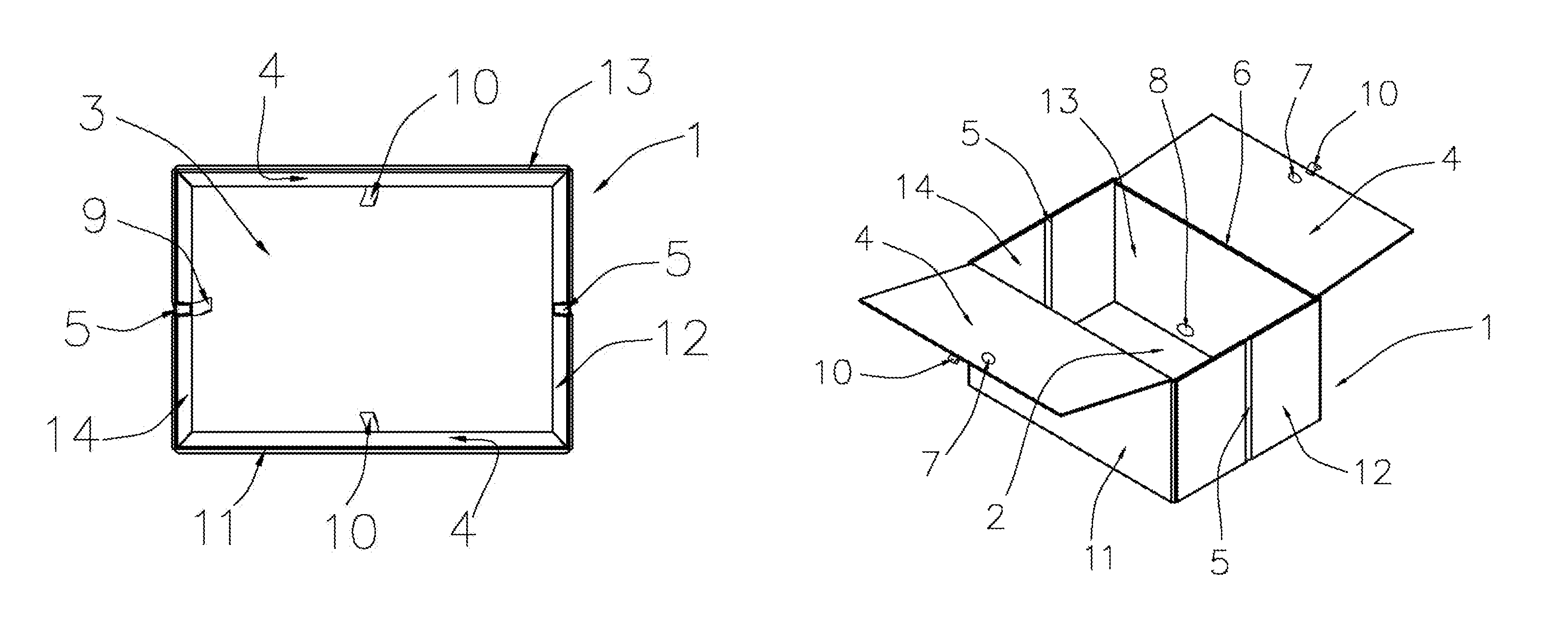
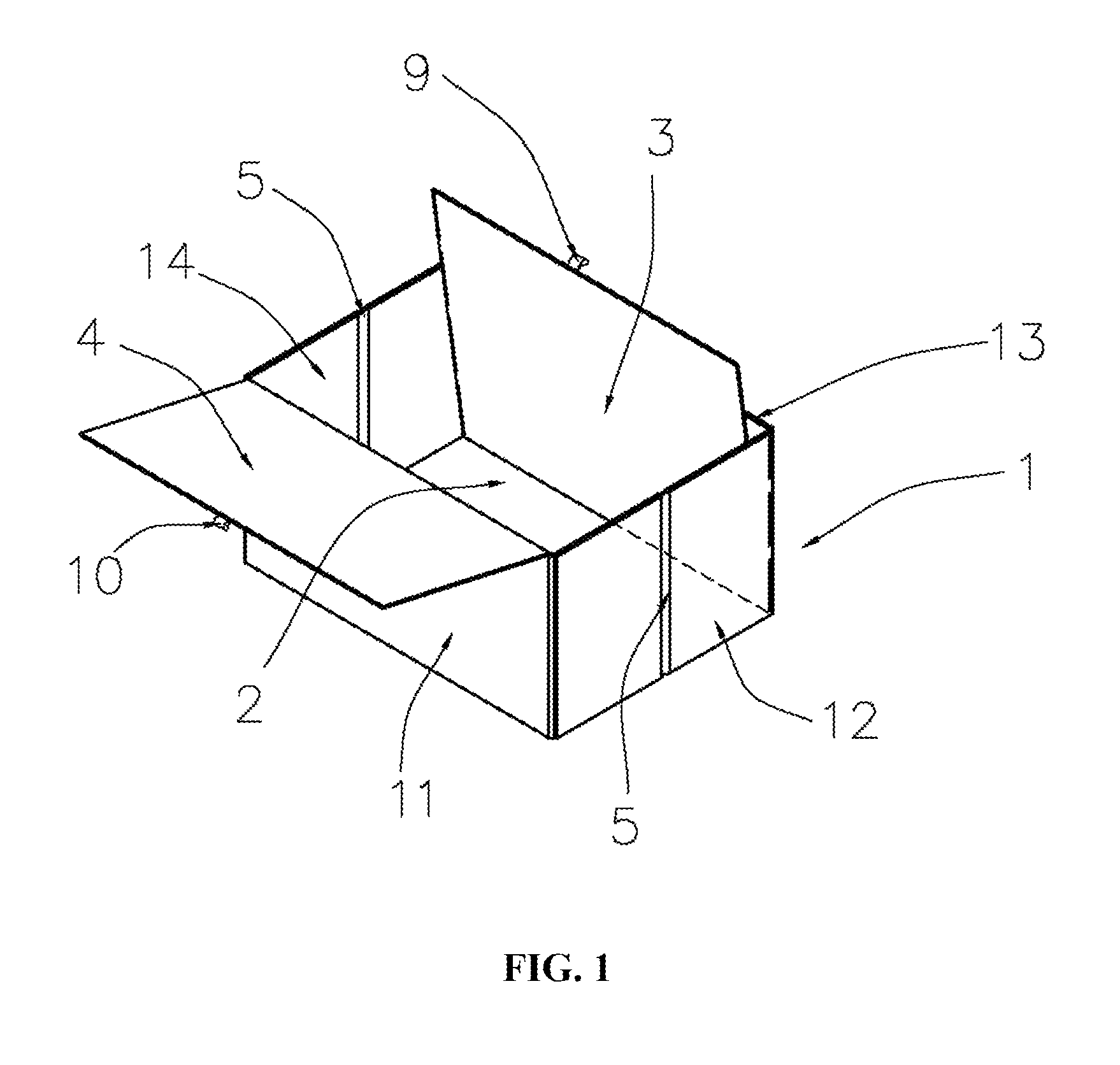
[0029]Referring to FIG. 1, a storage box comprises a foldable box main body 1, the bottom of which is provided with a substrate 2 made of soft material, and further comprises a soleplate 3 for supporting the box main body. The soleplate 3 is detachably disposed on the substrate 2. The box main body 1 is also movably connected with a lug plate 4 for resisting against the soleplate 3.

[0030]Specifically, the storage box in this embodiment comprises a soleplate 3 and a lug plate 4 for resisting against the soleplate 3. A left side plate 14 and a right side plate 12 disposed opposite to each other are symmetrically provided with a folding portion 5, respectively, so that the left side plate 14 and the right side plate 12 can be folded inward along the folding portions 5; and one side edge of the soleplate 3 is movably connected with the bottom of a front side plate 11 or a rear side plate 13 in a foldable way, and the rear side plate 13 or the front side plate 11 is connected with a lug ...

embodiment 2

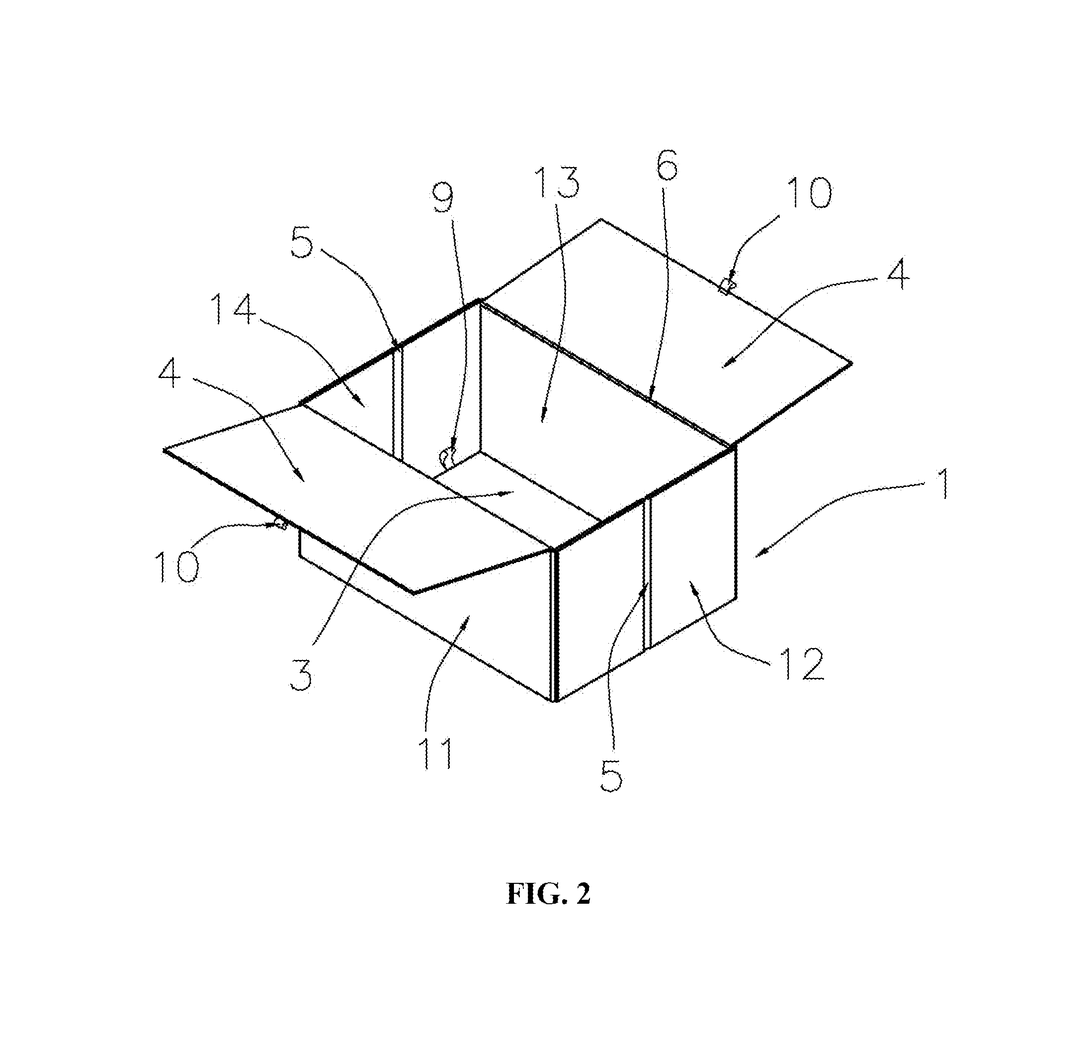
[0031]Referring to FIG. 2 to FIG. 4, the difference between this embodiment and Embodiment 1 is that: the soleplate 3 in this embodiment is detachably connected with the box main body 1 and may be taken out from the box main body 1, and four sides of the soleplate 3 when the storage box is unfolded for use are resisted against the side edges of the box main body 1.

[0032]Specifically, when the storage box needs to be used for accommodating articles, the soleplate 3 is placed inside the box main body 1, the soleplate 3 is placed on the upper surface of the substrate 2 in parallel, and four sides of the soleplate 3 are resisted against the front side plate 11, the right side plate 12, the rear side plate 13 and the left side plate 14, respectively, so that the box main body 1 is unfolded. Further, the lug plate 4 movably connected with the box main body 1 is resisted against and fix the soleplate 3, so that the soleplate 3 is firmly fixed between the substrate 2 and the lug plate 4. Ev...

embodiment 3

[0043]Referring to FIG. 5, the difference between this embodiment and Embodiment 2 is that: the storage box further comprises magnetic buttons for attracting the lug plates 4 with the front side plate 11 and the rear side plate 13, the magnetic buttons comprising auxiliary buttons 7 separately disposed on the two lug plates 4 and main buttons 8 separately disposed at corresponding positions on the front side plate 11 and the rear side plate 13, the auxiliary buttons 7 and the main buttons 8 being attracted together by the magnetism. The auxiliary buttons 7 and the main buttons 8 are preferably magnets attracted with each other. When the storage box disclosed by the present invention is unfolded for use, the arrangement of the magnetic buttons may make the two lug plates 4 further cling to the front side plate 11 and the rear side plate 13 closely, so that the firmness of the lug plates 4 resisting against the soleplate 3 is improved, the event of ineffective resisting caused by free...


PUM


Abstract

The invention relates to the technical field of supplies, in particular to a storage box, comprises a foldable box main body, the bottom of which is provided with a substrate made of soft material, and further comprising a soleplate supporting the box main body, the soleplate being detachably disposed on the substrate. The box main body is also movably connected with a lug plate for resisting against the soleplate. For the storage box disclosed by the invention, during transportation or when not in use, the box main body may be folded conveniently for storage, so that a small space is occupied and convenience and practicality are realized; and when the storage box is unfolded to accommodate articles, four edges of the soleplate placed inside the box main body are resisted against sides of the box main body so that the box main body is kept unfolded.

Description

FIELD OF THE INVENTION[0001]The present invention relates to the technical field of supplies, in particular to a storage box.BACKGROUND OF THE INVENTION[0002]As one of accommodation tools frequently used in daily work, life and learning, storage boxes may allow accommodation of office supplies, cosmetics, documents, small tools, clothes, shoes and other small items conveniently, so that people may enjoy more convenient, conformable, clean and tidy home life and work.[0003]There are various kinds of storage boxes at present. Although the storage boxes, made of hard material, have firm structure and also convenience in storage of articles, they may occupy a large space during the transportation or when not in use as they cannot be folded for storage; and, although the storage boxes, made of soft material, can be folded for storage, they have a disadvantage of poor stability. On this basis, storage boxes made of combination of hard material and soft material have been developed and res...

Claims


Application Information

Patent Timeline
Patent Type & Authority Patents(United States)
IPC IPC(8): B65D5/36B65D3/28A45C7/00
CPCB65D3/28A45C7/0036B65D5/36B65D5/326B65D5/4283
Inventor LEUNG, MING FUK
Owner LEUNG MING FUK
Learn More