Method and system for dynamic automated corrections to weather avoidance routes for aircraft in en route airspace

a technology of automatic correction and aircraft, applied in the field of en route trajectory rerouting of inflight aircraft for weather avoidance, can solve problems such as inability to fly, and achieve the effect of minimizing flying time delay, delay in computer processing time and human action

Active Publication Date: 2015-10-27
NASA
View PDF8 Cites 52 Cited by
  • Summary
  • Abstract
  • Description
  • Claims
  • Application Information

AI Technical Summary

Benefits of technology

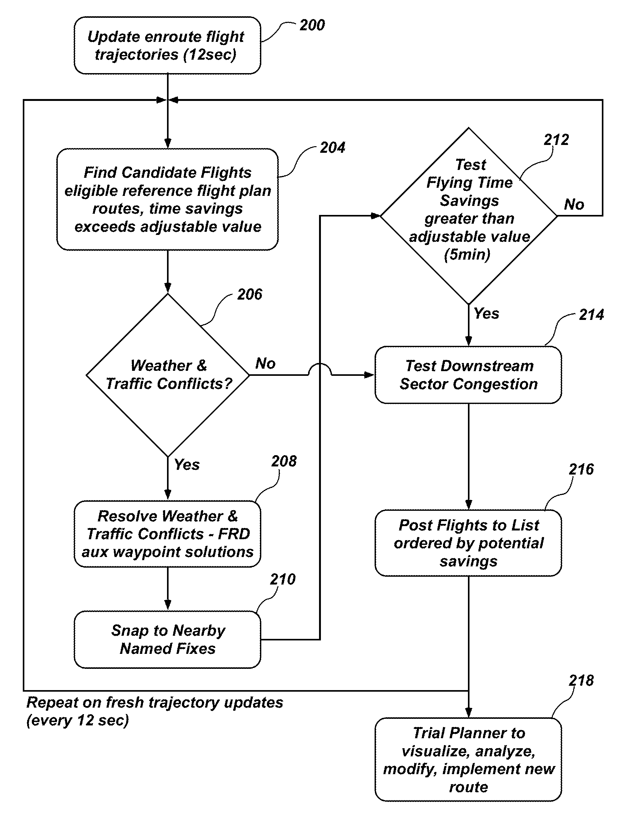
[0011]In accordance with still another illustrative aspect of the present invention, detecting weather and traffic conflicts may include testing reference routes for conflict with modeled weather and / or traffic. The step of resolving weather and traffic conflicts includes automatically forming candidate alternate routes that may include one or more inserted auxiliary waypoints to avoid current and forecast convective weather. The candidate alternate routes are between current positions and a downstream return capture fix optionally via one or more auxiliary waypoints. The step may also include selecting the candidate alternate route that have the minimum flying time delay relative to the preferred reference route and then testing the candidate alternate route to determine if it meets the flying time savings relative to the flight plan route to become the dynamic weather route. It is noted that, because an in-flight aircraft is traveling at a high rate of speed, the aircraft's “current position”, as the term is used in the present invention, includes positions just ahead of the aircraft, to allow for delays in computer processing time and human actions.
[0012]In accordance with yet another illustrative aspect of the present invention, selecting nearby named fixes may include replacing auxiliary waypoints of the candidate alternate route with nearby named fixes for ease of implementation and flying of such routes. The named fixes may be within, for example, 25 nautical miles of auxiliary waypoints originally computed using the more general fix-radial-distance (FRD) or latitude / longitude (LAT / LON) format. The selected nearby named fixes may be that combination of fixes that minimizes flying time delay relative to the initial candidate alternate route trajectory that was computed using the general FRD or LAT / LON format, while not resulting in a named-fix trajectory that conflicts with modeled weather.

Problems solved by technology

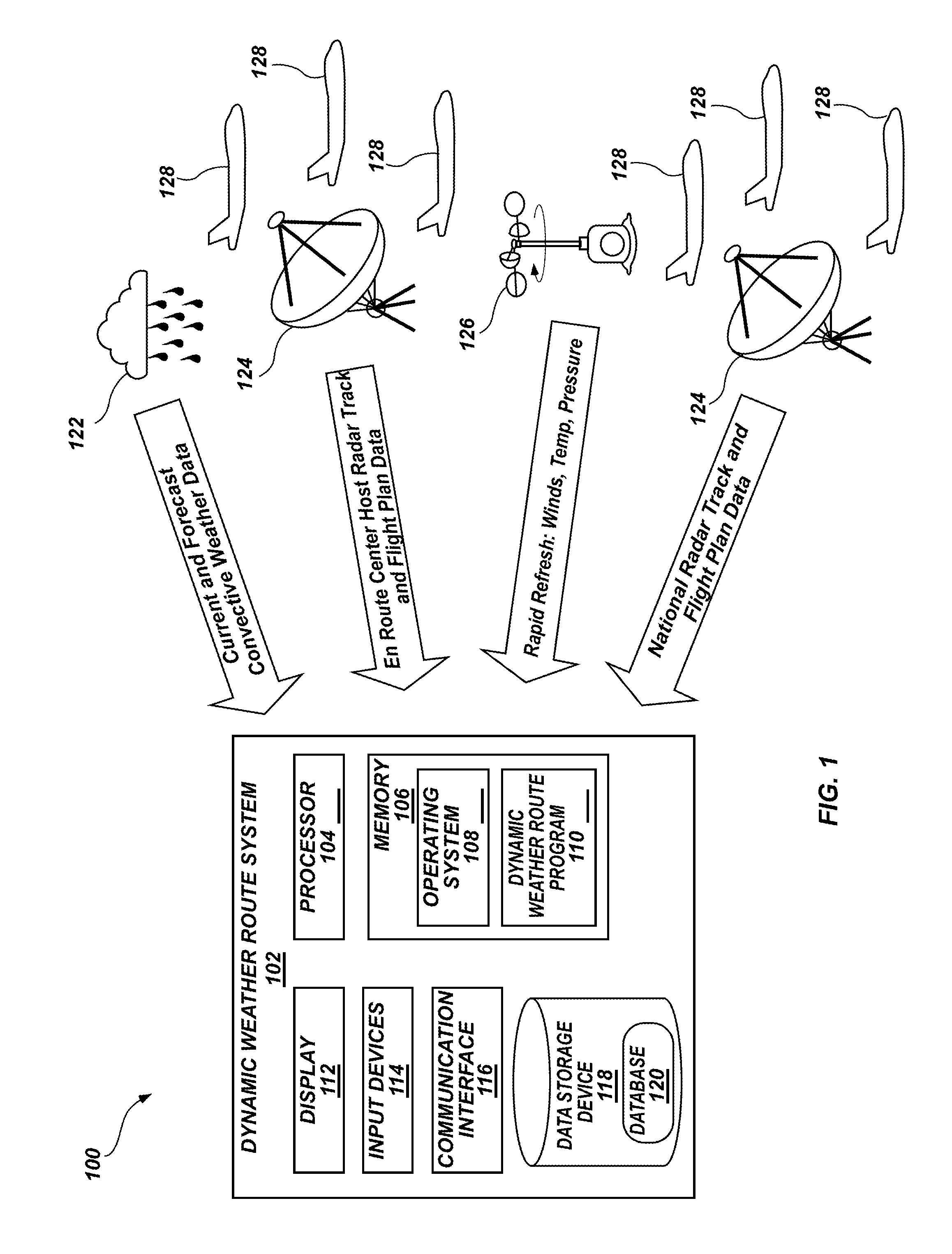
The step may also include identifying reference routes between current positions and downstream return capture fixes, where the reference routes eliminate large dog-legs and are generally more desirable routes as determined by their potential for wind-corrected flying time savings, but may not be flyable due to the presence of convective weather or traffic conflicts.

Method used


Image

  • Method and system for dynamic automated corrections to weather avoidance routes for aircraft in en route airspace
  • Method and system for dynamic automated corrections to weather avoidance routes for aircraft in en route airspace
  • Method and system for dynamic automated corrections to weather avoidance routes for aircraft in en route airspace

Examples


Embodiment Construction

[0030]For the purposes of promoting an understanding of the principles in accordance with the disclosure, reference will now be made to the illustrative embodiments illustrated in the drawings, and specific language will be used to describe them. It will nevertheless be understood that no limitation of the scope of the disclosure is thereby intended. Any alterations and further modifications of the inventive features illustrated herein, and any additional applications of the principles of the disclosure as illustrated herein, which would normally occur to one skilled in the relevant art and having possession of this disclosure, are to be considered within the scope of the disclosure claimed.

[0031]It must be noted that, as used in this specification and the appended claims, the singular forms “a,”“an,” and “the” include plural referents unless the context clearly dictates otherwise. As used herein, the terms “comprising,”“including,”“having,”“containing,”“characterized by,” and gramm...


PUM


Abstract

A dynamic weather route system automatically analyzes routes for in-flight aircraft flying in convective weather regions and attempts to find more time and fuel efficient reroutes around current and predicted weather cells. The dynamic weather route system continuously analyzes all flights and provides reroute advisories that are dynamically updated in real time while the aircraft are in flight. The dynamic weather route system includes a graphical user interface that allows users to visualize, evaluate, modify if necessary, and implement proposed reroutes.

Description

CROSS-REFERENCE TO RELATED APPLICATIONS[0001]This application claims the benefit of U.S. Provisional Application Nos. 61 / 567,604 and 61 / 664,489, filed Dec. 6, 2011 and Jun. 26, 2012, respectively, which are hereby incorporated by reference herein in their entirety.ORIGIN OF INVENTION[0002]The invention described herein was made by employees of the United States Government and may be manufactured and used by or for the Government of the United States of America for governmental purposes without the payment of any royalties thereon or therefor.BACKGROUND OF INVENTION[0003]1. Technical Field of the Invention[0004]This invention relates generally to the field of en-route trajectory re-routing of in-flight aircraft for weather avoidance, and more particularly, to computer automated trajectory re-routing of in-flight aircraft around convective weather for more efficient time-saving and fuel-saving weather-avoidance route corrections.[0005]2. Description of Related Art[0006]Weather is the ...

Claims


Application Information

Patent Timeline
Patent Type & Authority Patents(United States)
IPC IPC(8): G06F19/00G06G7/76G06G7/70G01C21/00G01C21/34G08G1/123G08G5/00
CPCG08G5/003G08G5/0013G08G5/0039G08G5/0095
Inventor MCNALLY, B. DAVIDERZBERGER, HEINZSHETH, KAPIL
Owner NASA
Why Eureka
Try Eureka