Electric pruner with a quick-release mechanism

a quick-release mechanism and electric pruner technology, applied in the field of electric pruners, can solve the problems of easy wear of the moving blade, troublesome replacement work, adversely affecting the cutting efficiency and cutting effect, etc., and achieve the effect of simple replacement work and convenient us

Active Publication Date: 2015-11-10
CHERVON HK LTD WANCHAI
View PDF18 Cites 5 Cited by
  • Summary
  • Abstract
  • Description
  • Claims
  • Application Information

AI Technical Summary

Benefits of technology

[0007]To solve at least some of the above problems, the presently disclosed electric pruner provides a device wherein the replacement of the movable blade is simple and convenient, avoiding the requirement of removing any part.
[0009]With the above arrangements, when the movable blade needs to be replaced, the user only needs to directly operate the locking device to switch it to the released position, the movable blade would then be unlocked. Once unlocked, the movable blade can be directly pulled out by the user for replacement. When installing a new movable blade, the user only needs to insert the movable blade into the housing and then return the locking device to the locked position, then the movable blade is locked. During the whole replacement course of the blade, it is not necessary for the user to remove any part and to use any other auxiliary tools. Because the directly manual operation of the locking device would lock or release the movable blade, the replacement work is very simple and convenient.

Problems solved by technology

Typically, however, because the movable blade has a small cutting edge angle and is relatively thin, the movable blade is easy worn.
As a result, the cutting edge of the movable blade can become blunt, which adversely affects the cutting efficiency and the cutting effect.
Currently, for most of electric pruners on the market, it is oftentimes necessary to detach the housing when replacing the movable blade, and thus the replacement work is very troublesome.
Although it is not necessary to detach the housing for a very few kinds of electric punning shears, it is still necessary to remove the bolts connecting the movable blade and the fixed blade, and the steps for replacing the blade are still troublesome.

Method used


Image

  • Electric pruner with a quick-release mechanism
  • Electric pruner with a quick-release mechanism
  • Electric pruner with a quick-release mechanism

Examples


Embodiment Construction

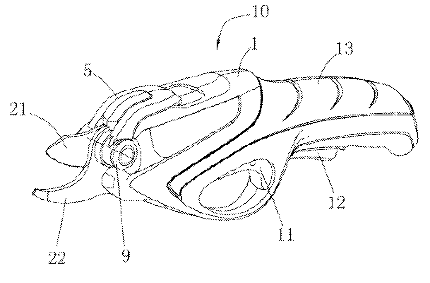
[0019]FIG. 1 is a perspective view of one example electric pruner in accordance with the teachings of the present disclosure. As shown in FIG. 1, the electric pruner 10 comprises a housing 1 including a motor 14, a transmission mechanism 3, and a built-in battery (not shown) accommodated within the housing 1. A switching trigger 11 and a safety switch 12 are mounted under the housing 1 so as to control the motor 14. A gripping portion 13 is formed by the rear portion of the housing 1. A movable blade 21 and a fixed blade 22 extend from the front end of the housing 1, wherein the fixed blade 22 is fixedly mounted in the housing 1 by a bolt or the like, and the movable blade 21 is rotatably connected to the fixed blade 22 by a shaft 4. In the present example, the shaft 4 is embodied as a bolt.

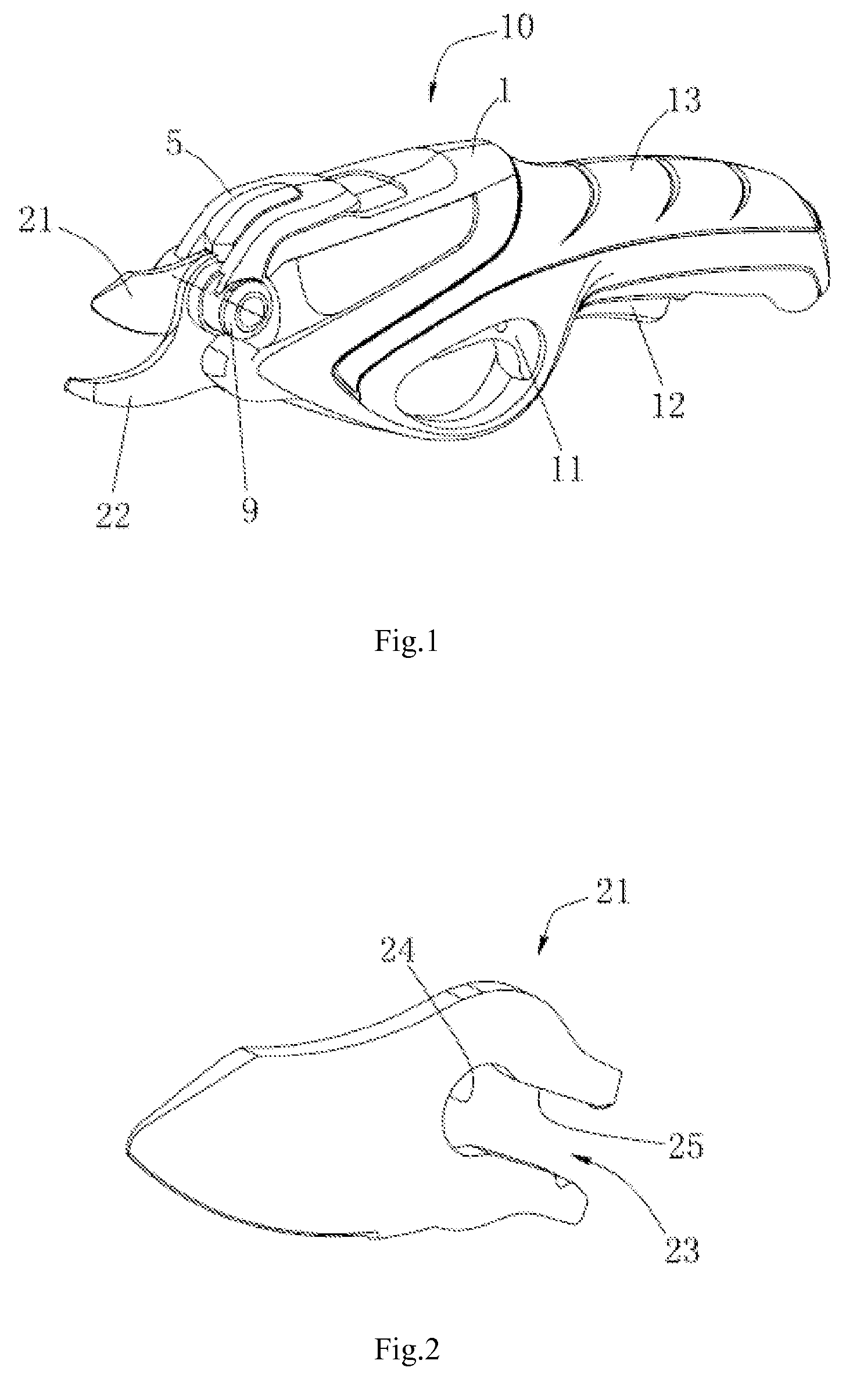
[0020]As shown in FIG. 2, the movable blade 21 is provided with a groove 23 which comprises a first groove portion 24 and a second groove portion 25 in communication with each other. The first gr...


PUM


Abstract

An electric pruner includes a housing, a motor accommodated within the housing, a transmission mechanism, a movable blade, and a fixed blade extending from the front end of the housing. The fixed blade is fixedly mounted on the housing, and the movable blade is rotatably connected to the fixed blade via a shaft and driven by the motor via the transmission mechanism. A locking device manually operable by the user is arranged on the shaft for locking the movable blade, the locking device being switchable between a first position where the movable blade is locked to stay connected with the transmission mechanism and a second position where the movable blade is releasable from the transmission mechanism. Thus, the replacement of the movable blade is very simple and convenient.

Description

CROSS REFERENCE TO RELATED APPLICATION[0001]This application is a non-provisional application claiming priority from Chinese Application CN 201110206372.6, filed on Jul. 22, 2011, the disclosure of which is incorporated herein by reference in its entirety.FIELD OF THE DISCLOSURE[0002]The present description relates generally to an electric pruner and, more particularly, to a quick replacing structure for the blade of the electric pruner.BACKGROUND OF RELATED ART[0003]As a kind of garden tool, the electric pruner is often used during garden pruning due to its compact size and simple portability. This kind of the electric pruner comprises a movable blade and a fixed blade fixedly mounted on the housing, wherein the movable blade is rotatably connected to the fixed blade and can be driven by a motor via a transmission mechanism to swing back and forth so as to perform cutting.[0004]During operation, the fixed blade provides support, and the movable blade serves to cut. Typically, howev...

Claims


Application Information

Patent Timeline
Patent Type & Authority Patents(United States)
IPC IPC(8): B26B13/04B26B15/00A01G3/037
CPCA01G3/037B26B13/04B26B15/00
Inventor YAMAOKA, TOSHINARIZHANG, QI
Owner CHERVON HK LTD WANCHAI
Why Eureka
Try Eureka