Tent frame coupler assembly

a tent frame and coupler technology, applied in tents/canopies, building types, constructions, etc., can solve the problems of not being able to contain longitudinally, not being able to easily accommodate cabin tents, and other coverings of tents of this type that require a strong framework, etc., to achieve stable vertical support

Inactive Publication Date: 2015-11-10
SCHAEFER GARY
View PDF16 Cites 11 Cited by
  • Summary
  • Abstract
  • Description
  • Claims
  • Application Information

AI Technical Summary

Benefits of technology

[0028]Each hinge, web or wing arm arcuately radiates from a sidewall of each sleeve piece and is aligned to overlap in parallel alignment to a mating hinge arm of the interconnected hinged sleeve arm. The overlapping arcuate wing arms include serrated interlocking surfaces. Upon inserting a pivot or hinge pole section through the bores of the overlapped closed eyelet-type end collars at each hinged sleeve arm and drawing and fastening the overlapping wing arms together with suitable fasteners, the splayed pole pieces extending from each sleeve piece provides a stable vertical support for the interconnected horizontal pole pieces (e.g. ridge pole).

Problems solved by technology

The fabric and other coverings for tents of this type however are relatively heavy and require a strong framework.
Although the '698 system adequately supports a tent and is susceptible to volume production with modular couplers, the couplers do not readily accommodate cabin style tents.
The couplers support the poles only in a single plane and are not able to contain longitudinal support poles, which are desired in a self-supporting framework.

Method used


Image

  • Tent frame coupler assembly
  • Tent frame coupler assembly
  • Tent frame coupler assembly

Examples


Embodiment Construction

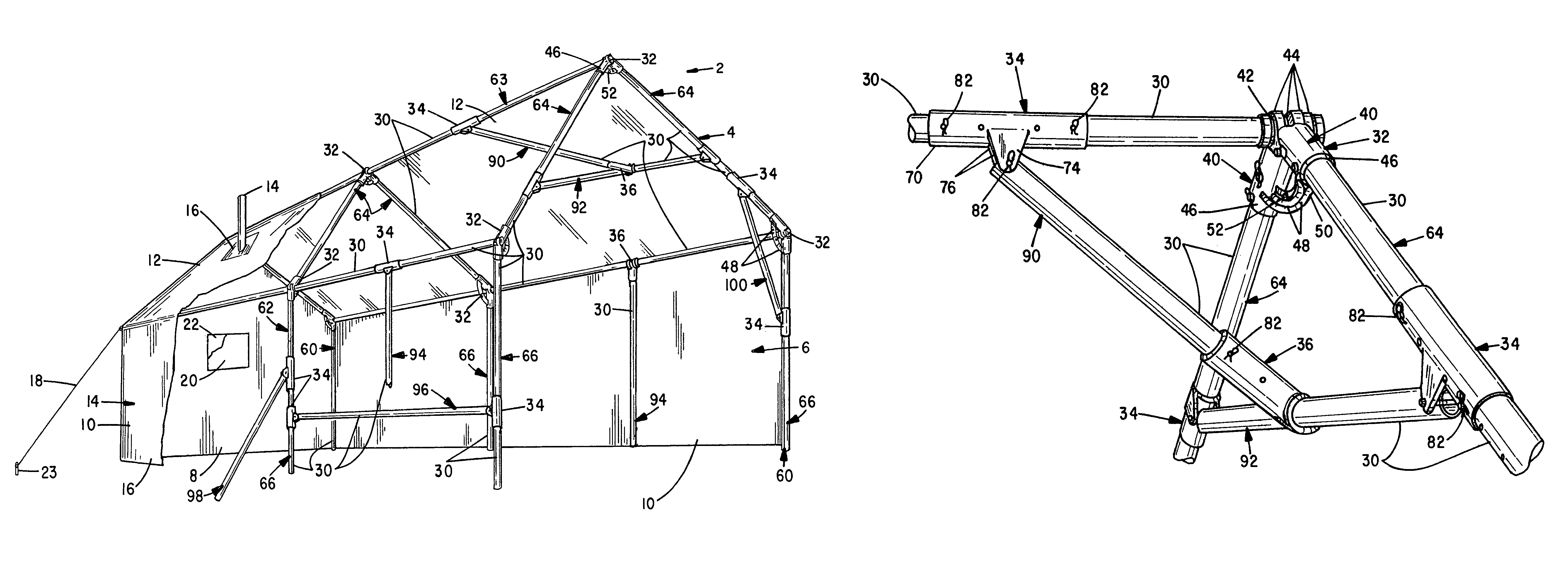
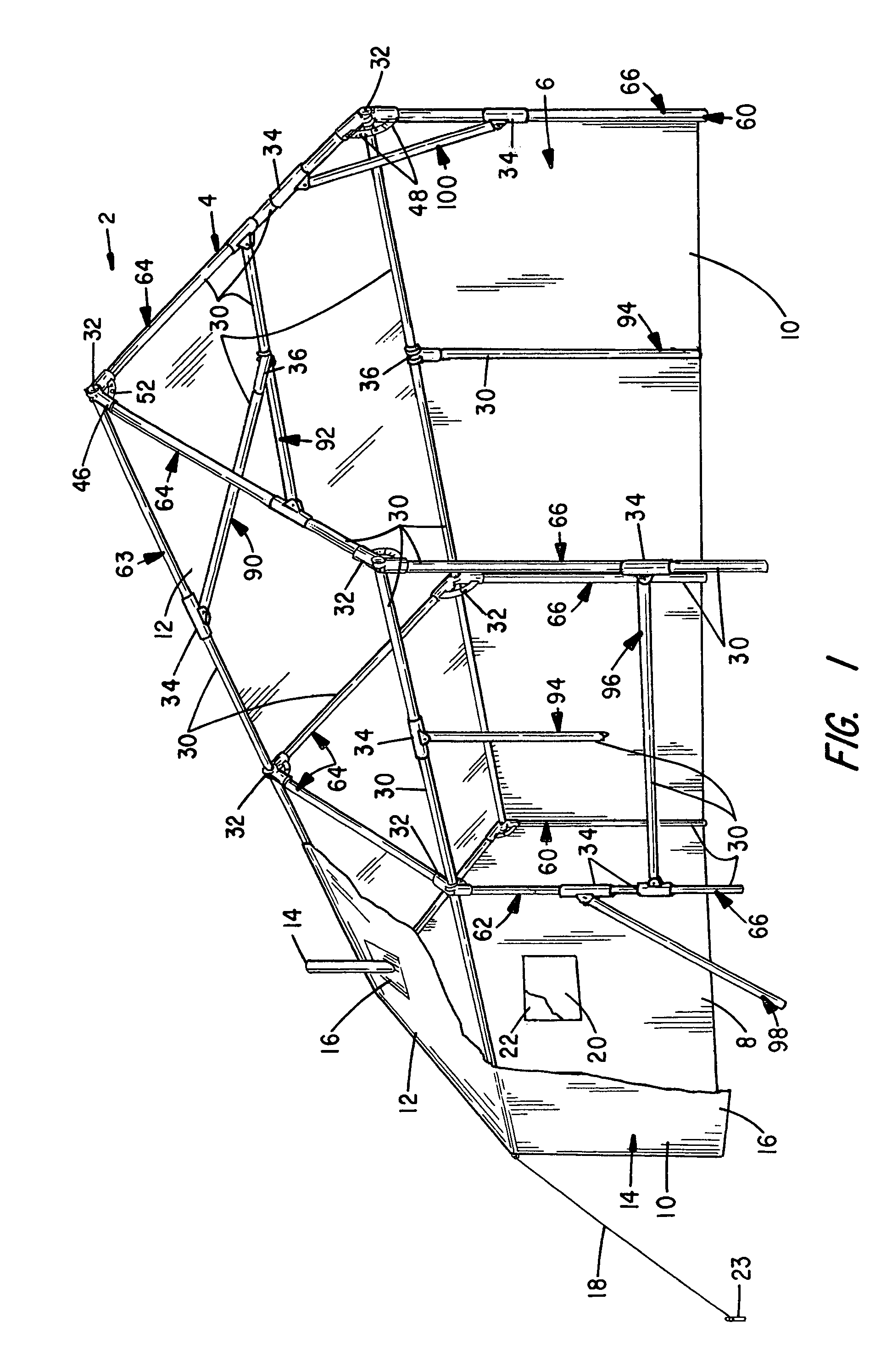
[0035]Referring to FIG. 1, a perspective drawing is shown to a typical self-supported wall tent 2. The tent 2 includes a support framework 4 that supports a fabric cover 6 sewn to provide a pair of end walls 8 (only one of which is shown), side walls 10, and splayed ceiling walls 12.

[0036]The cover 6 is constructed from a suitable grade of canvas or other waterproof material to resist wind, rain and snow. Depending upon the tent size, a number of fabric panels are sewn together to form the walls 8 and 10 and ceiling 12. A chimney 14 is mounted through a fireproof panel 16. Door access flaps with closure fasteners (not shown) are provided at one or both end walls 8 or can also be provided at the side walls 10. External tie down straps 18 are provided as required to stabilize the tent 2. Windows 20 and cover flaps 22 (shown in partial cutaway) may also be provided. Although one wall tent construction is shown, it is to be appreciated a variety of other shapes, sizes and arrangements o...


PUM


Abstract

A self-supporting tent support framework. The framework includes a number of support poles that interconnect at hinge, clevis / saddle and T / collar couplers to adjustably support the poles. The couplers retain the poles at user established angular orientations in multiple planes to support an overlying fabric cover. Each hinge coupler includes a pair of hinge pieces having a tubular sleeve body, an end collar that receives a transecting pivot pole and projecting wing arms overlap and fasten to support body mounted poles at an adjustable splay angle. Each clevis / saddle coupler includes a tubular sleeve body having depending parallel clevis arms that pivotally secure a pole to the clevis arms relative to a pole fitted to the sleeve body. Each T / collar coupler includes a tubular sleeve body and a pair of displaced, parallel coaxially projecting end collars having enclosed transverse coaxial through bores to adjustably support a T-aligned pole section.

Description

BACKGROUND OF THE INVENTION[0001]The present invention relates to tent support framework systems and, in particular, to a multi-sectional tubular self-supporting framework assembly wherein a plurality of tubular pole pieces or sections are secured together with appropriate radially adjustable hinge couplers, in-line clevis / saddle couplers and “T or collar” couplers that longitudinally and transversely interconnect the tubular pole pieces to define a desired support framework.[0002]With the increasing popularity of outdoor activities, a resurgence of interest has occurred in the camping industry. A variety of designs for stable, collapsible frame tents have evolved to meet this demand. Such tents are designed to meet the needs of a variety of users from backpackers, to weekend campers, who camp from their vehicle, to outfitted camps that are established in remote sites from horseback or four-wheeled vehicles.[0003]Many tent support frames utilize a number of small diameter (i.e. less...

Claims


Application Information

Patent Timeline
Patent Type & Authority Patents(United States)
IPC IPC(8): E04H15/34E04H15/52E04H15/44
CPCE04H15/34E04H15/44E04H15/52
Inventor SCHAEFER, GARY
Owner SCHAEFER GARY
Why Eureka
Try Eureka