Shock absorption and energy consumption type outrigger truss high-rise structure system

An outrigger truss and high-rise structure technology is applied in the field of shock absorption and energy consumption type outrigger truss high-rise structure system, which can solve the problems of lack of auxiliary return structure, uneven structural rigidity, no rigidity of viscous damper, etc. The ability to reduce force, shock absorption and reset, facilitate installation and maintenance costs, and reduce the effect of large shaking

Active Publication Date: 2022-03-18
中城建(福建)建筑设计研究院有限公司
View PDF6 Cites 3 Cited by
  • Summary
  • Abstract
  • Description
  • Claims
  • Application Information

AI Technical Summary

Problems solved by technology

[0008] The purpose of the present invention is to provide a high-rise structure system of shock-absorbing and energy-consuming outrigger truss, based on the existing technology of shock-absorbing and energy-consuming outrigger truss structure, to solve the problem that the traditional outrigger truss has too much influence on the stiffness of the core shear wall of the floor. Large, after the reinforcement layer is set, it is easy to cause uneven stiffness of the structure along the height direction, and the sudden change of the stiffness will bring about a sudden change of the internal force. The viscous damper has no stiffness under the static load, and the dynamic stiffness under the earthquake is small, and its energy dissipation capacity cannot keep up with the earthquake. Intensity increased significantly, and the lack of auxiliary return structure in the existing technology

Method used


Image

  • Shock absorption and energy consumption type outrigger truss high-rise structure system
  • Shock absorption and energy consumption type outrigger truss high-rise structure system
  • Shock absorption and energy consumption type outrigger truss high-rise structure system

Examples


Embodiment Construction

[0045] The above solution will be further described below in conjunction with specific embodiments. It should be understood that these examples are used to illustrate the present invention and not to limit the scope of the present invention. The implementation conditions used in the examples can be further adjusted according to specific conditions, and the implementation conditions not indicated are usually the conditions in routine experiments.

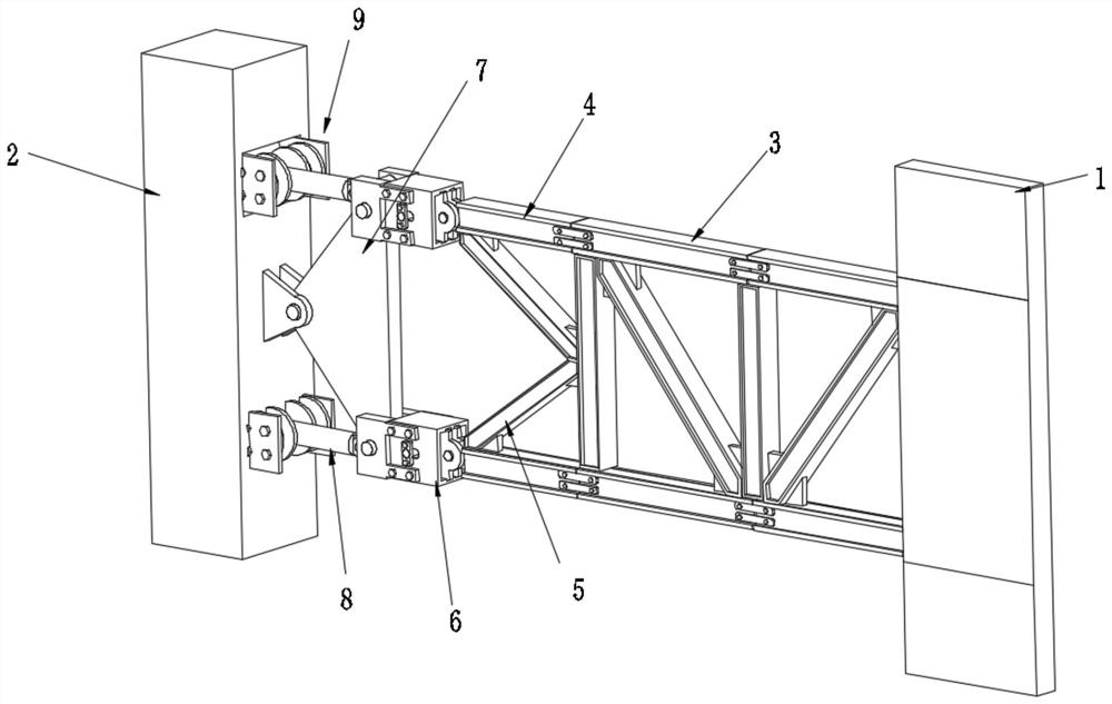
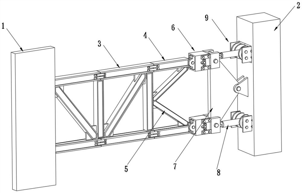
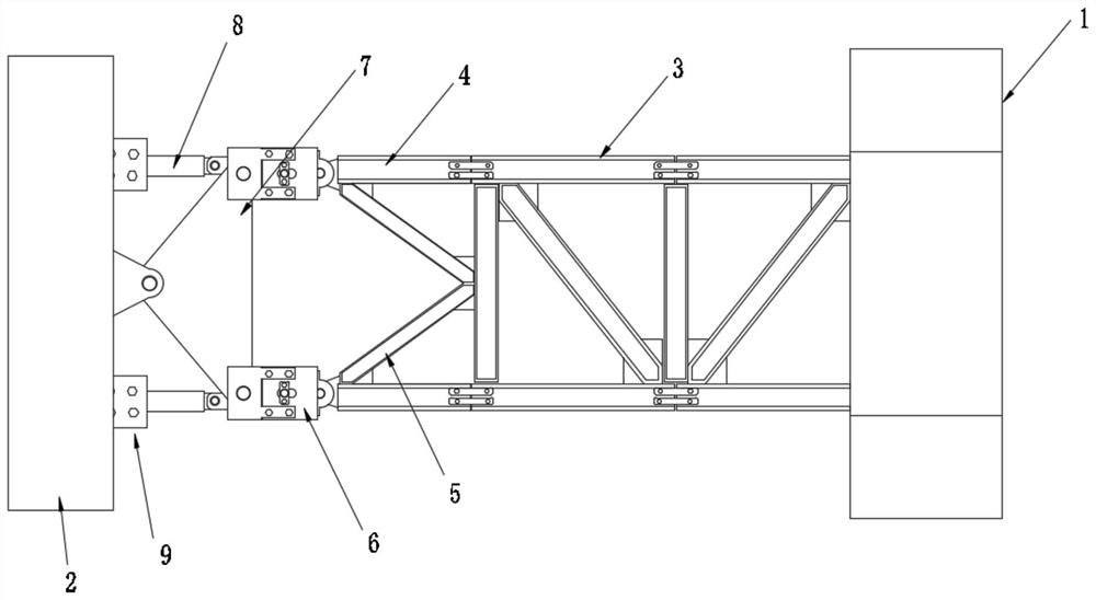
[0046] like figure 1 , figure 2 , image 3 , Figure 4 , Image 6 , Figure 7 , Figure 8 , Figure 9 , Figure 10 As shown, a high-rise structure system of shock-absorbing and energy-dissipating outrigger trusses, including core shear walls 1, giant steel concrete columns 2, outrigger trusses 3, truss rods 4, chord rods 5, shock-absorbing components 6, and amplification devices 7. Viscous damper 8 and vertical support assembly 9, one side of the core shear wall 1 is provided with an outrigger truss 3 and two truss rods 4 a...


PUM


Abstract

The invention discloses a shock absorption and energy dissipation type outrigger truss high-rise structure system which comprises a core shear wall, giant steel concrete columns, outrigger trusses, truss rods, chord members, shock absorption assemblies, amplification devices, viscous dampers and vertical supporting assemblies. The outrigger trusses are arranged on one side of the core shear wall, the truss rods and the chord members are arranged on one side of the outrigger trusses, and the vibration absorption assemblies are arranged on the other side of the outrigger trusses. A damping assembly, an amplifying device and a viscous damper are arranged at one end of the truss rod, and one end of the viscous damper is fixed in the giant steel concrete column through a vertical supporting assembly; according to the damping assembly, preliminary damping is conducted on kinetic energy, generated by earthquakes and wind, of a super high-rise building, the torque is amplified through the amplifying device so that the force eliminating and damping functions of a viscous damper can be fully achieved, the rigidity of the viscous damper can be in a dynamic state, and the damping and energy dissipation functions of the viscous damper can still be achieved in the small earthquake or weak wind environment; the lead core rubber seat is adopted to provide stable vertical support, and the structure can assist in returning the building after the stilling work is completed.

Description

technical field [0001] The application of the present invention relates to the technical field of engineering construction, in particular to a high-rise structure system of a shock-absorbing and energy-consuming outrigger truss. Background technique [0002] Earthquake action and wind load action are the two most prominent factors in the design of super high-rise buildings. Under the action of earthquake and wind force, structural deformation and wind-resistant comfort should not exceed the limit specified in the code, which is the focus and difficulty of high-rise design. Most super high-rise structures use the outer frame column and the middle core tube structure system. Outrigger trusses are arranged at a certain floor height between the outer frame column and the inner core tube. When the structure is subjected to horizontal loads, the core is adjusted through the coordination of the outrigger truss One side of the peripheral frame column is under compression and the ot...

Claims


Application Information

Patent Timeline
Patent Type & Authority Applications(China)
IPC IPC(8): E04C3/04E04B1/98E04H9/02E04B1/36E04B1/58
CPCE04C3/04E04B1/98E04H9/021E04B1/36E04B1/58E04C2003/0486Y02A30/30
Inventor 章亚光冯望
Owner 中城建(福建)建筑设计研究院有限公司
Why Eureka
Try Eureka