
Fan-holding equipment and mobile waterborne platform

A technology for operating platforms and lifting devices, which is applied in the field of wind turbine lifting devices and mobile water work platforms, and can solve the problems of high stability requirements for crane ships, high costs for using or renting crane ships, and weather-affected operating time And other issues

Inactive Publication Date: 2011-06-01
SANY ELECTRIC CO LTD
View PDF3 Cites 28 Cited by
  • Summary
  • Abstract
  • Description
  • Claims
  • Application Information

AI Technical Summary

Problems solved by technology

[0007] When the fan is installed in this way, the crane ship is in a floating state, and the stability of the ship is poor. When the fan is hoisted from the top of the fan by the high and long boom of the crane ship, the shaking of the hull will amplify the shaking effect on the fan , the fan is always in a shaking state, making it difficult to align the installation part of the bottom of the fan tower with the installation part of the fan foundation of the wind farm, making the installation of the fan very difficult
Therefore, in the process of hoisting the wind turbine as a whole, the stability of the crane ship is highly required, which leads to the installation of the wind turbine only in calm weather, and the working time is greatly affected by the weather
[0008] Moreover, large-scale crane ships are not dedicated to wind turbine installation, and the cost of using or renting crane ships is very high, which in turn leads to higher wind turbine installation costs
In addition, large cranes also have the characteristics of deep draft, so large cranes cannot be used for hoisting operations in tidal flats or shallow sea areas, so that the application of this method is limited by the installation area

Method used


Image

  • Fan-holding equipment and mobile waterborne platform
  • Fan-holding equipment and mobile waterborne platform
  • Fan-holding equipment and mobile waterborne platform

Examples


Embodiment Construction

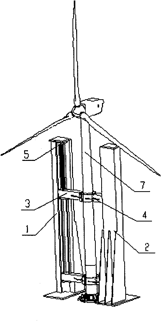
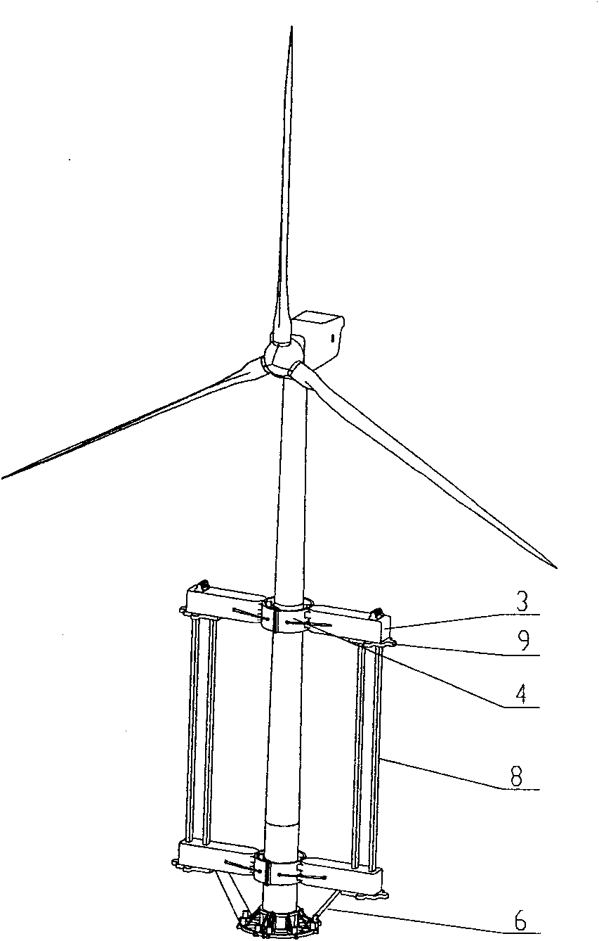
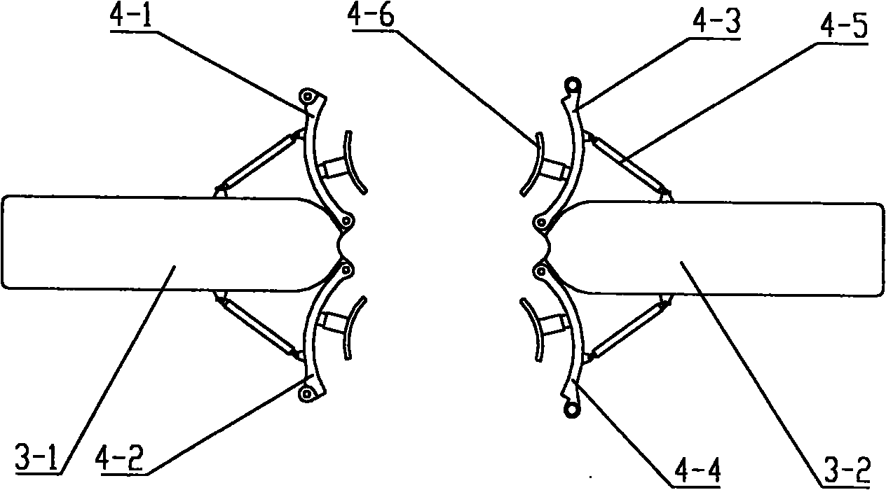
[0058] One of the cores of the present invention is to provide a fan holding and lifting device, which can be used for a mobile water work platform, and can fix the assembled whole fan on the mobile water work platform according to the installation state of the fan, When the mobile water work platform moves to the wind turbine foundation position of the wind farm, the wind turbine holding and lifting device moves to the position aligned with the wind turbine foundation to realize the installation of the wind turbine. The second core of the present invention is to provide a mobile water work platform.

[0059] The content of the present invention will be described below with reference to the accompanying drawings. The following description is only exemplary and explanatory, and should not have any limiting effect on the protection scope of the present invention.

[0060] see figure 1 , figure 1 It is a schematic structural diagram of a specific implementation manner of the fa...


PUM


Abstract

The invention relates to the technical field of installation of offshore fans and discloses fan-holding equipment. The fan-holding equipment is used on the mobile operating platform above water, including a first column, a second column, beam lifting equipment, at least one beam and a holding equipment to hold the fan tower. The first column and the second column are set side by side, and guide slots for the at least one beam to slide are arranged opposite to the first column and the second column. The holding-equipment is arranged on the at least one beam, and both ends of the at least one beam are clamped in the guide slots of the first column and the second column. The beam lifting equipment is fixed on the first column or second column, and the lifting end of the beam lifting equipment is connected to the beam. The fan-holding equipment can fix the equipped whole fan according to the fan installation status, and can realize the lifting and dropping of the fan. The invention also discloses a mobile operating platform above water.

Description

technical field [0001] The invention relates to the technical field of offshore wind turbine installation, in particular to a wind turbine holding and lifting device for a mobile water work platform. The invention also relates to a mobile water work platform. Background technique [0002] Offshore wind power generation technology is a technology that builds a wind farm on an appropriate sea area, installs one or more wind turbines on the foundation of the wind farm, and converts wind energy into electrical energy through the wind turbine. The fan generally includes a fan tower, a wind wheel and a nacelle, and a generator, a gearbox, and a main shaft are installed in the nacelle. The bottom end of the fan tower is installed on the fan foundation of the wind farm, and the wind wheel and the nacelle are installed on the top of the wind turbine tower. conversion. [0003] Generally speaking, each part of the fan has a large weight. For example, the overall weight of the fan c...

Claims


Application Information

Patent Timeline
Patent Type & Authority Applications(China)
IPC IPC(8): B66C1/42E02B17/00
CPCF03D1/005F05B2240/93Y02E10/72F05B2240/95Y02E10/727F03D1/001F03D13/25E02B2017/0039E02B2017/0043E02B2017/0047E02B2017/0091F03D13/10F03D13/40
Inventor 吴佳粱王新明李艳林白俊磊
Owner SANY ELECTRIC CO LTD
Learn More