

Connection arrangement from hollow steel sections which are subject to axial pressure
a technology of axial pressure and connection arrangement, which is applied in the direction of rod connection, furniture joining, structural elements, etc., can solve the problems of high effort and high cost of connection techniques, and achieve the effect of cost effective and fast production
- Summary
- Abstract
- Description
- Claims
- Application Information
AI Technical Summary
Benefits of technology
Problems solved by technology
Method used
Image

Examples
Embodiment Construction
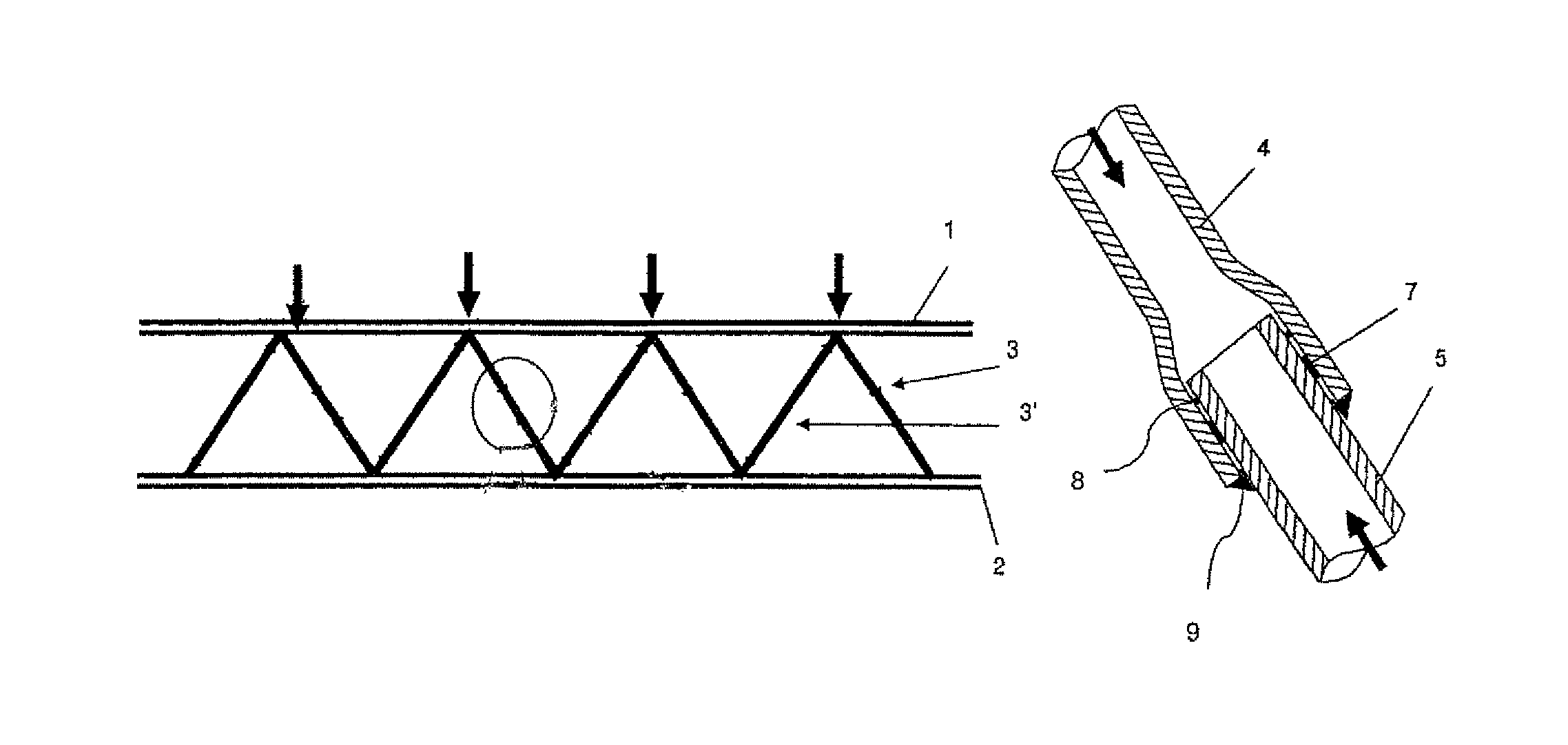
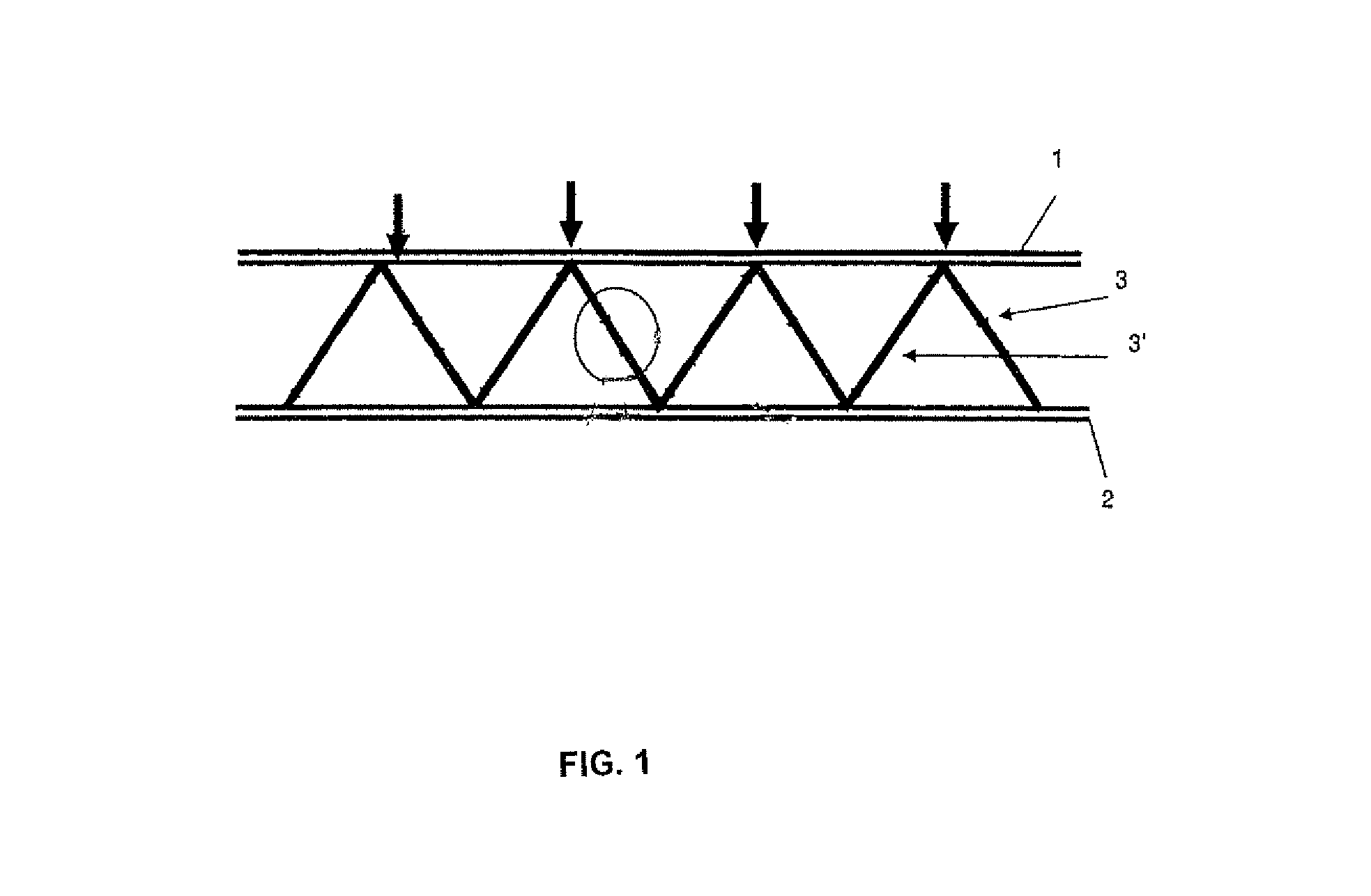
[0025]FIG. 1 shows a framework construction according to the invention which has been produced from hollow sections with an upper chord 1, a lower chord 2 and diagonal beams 3, 3′ as support elements. The support elements themselves are composed of seamlessly rolled hollow sections, which are connected to one another to multiple lengths according to the required length.
[0026]In framework constructions which are subjected to load (see load arrows) the diagonal beams 3, 3′ behave as pressure bar 3 or respectively, tension 3′ bar. In diagonal beams which, due to the required length are subdivided, the connections of the beams which are only subjected to axial pressure are configured as form-fitting plug-in connection. The other support elements of the framework construction on the other hand, are connected to one another in a conventional manner with welded on head plate connections (not shown here), so that tensile loads can be absorbed by the connection.
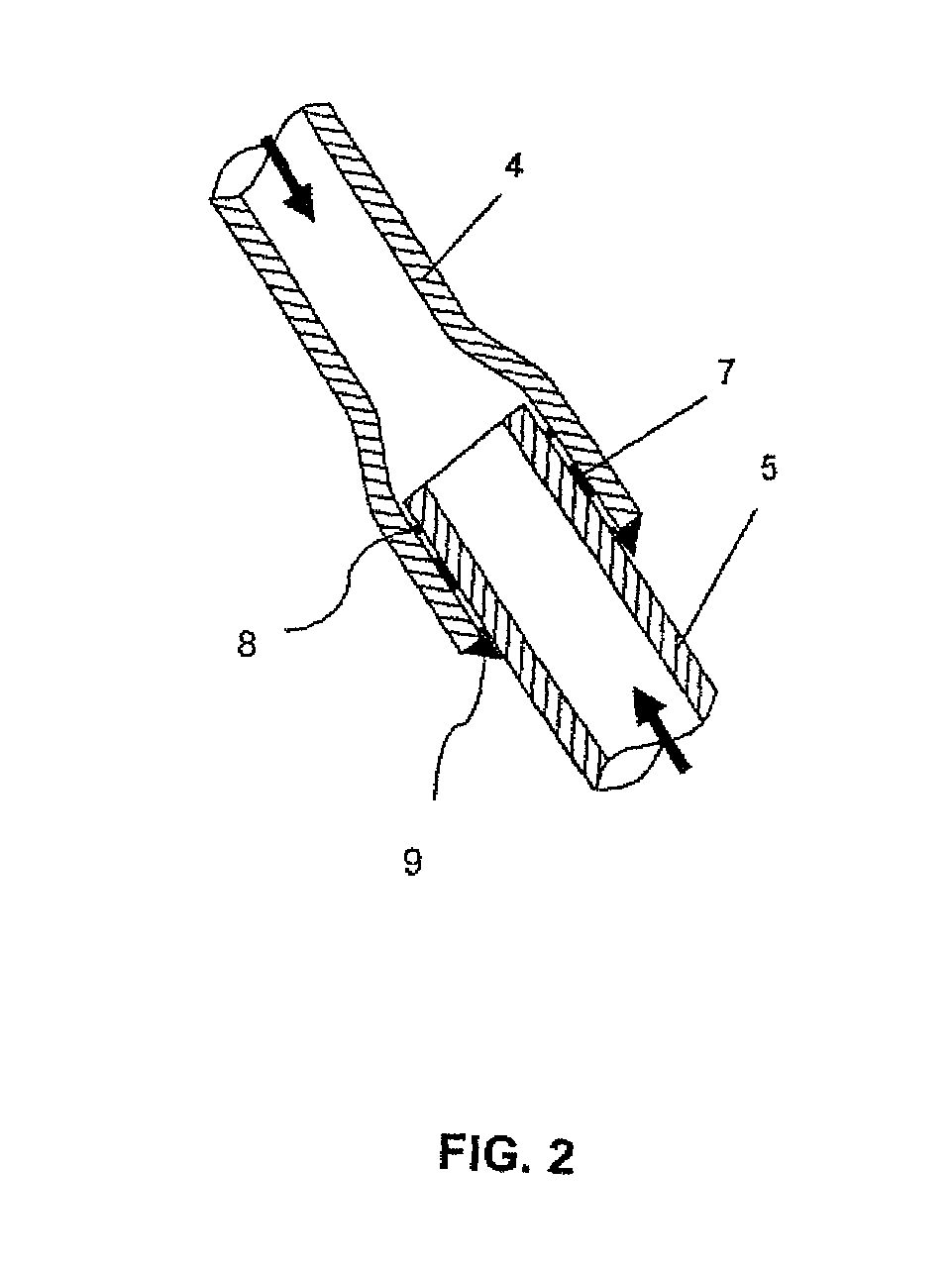
[0027]FIG. 2 shows an embodime...
PUM
 Abstract
Description
Claims
Application Information