
Liquid crystal display and method of optical compensation thereof

a liquid crystal display and optical compensation technology, applied in non-linear optics, instruments, optics, etc., can solve the problems of severe dark-state light leakage phenomenon poor contrast at a large viewing angle, and increasing display quality requirements for liquid crystal display panels. , to achieve the effect of small viewing angle range, large viewing angle and poor contras

Active Publication Date: 2015-11-17
TCL CHINA STAR OPTOELECTRONICS TECH CO LTD
View PDF1 Cites 1 Cited by
  • Summary
  • Abstract
  • Description
  • Claims
  • Application Information

AI Technical Summary

Benefits of technology

[0011]The present invention provides a liquid crystal display and a method of optical compensation thereof to resolve the technology problems of severe dark-state light leakage phenomenon at a large viewing angle caused by adopting an A-plate and a C-plate having compensation values according to the prior art, poor contrast at a large viewing angle, and small viewing angle range.
[0038]In contrast to the prior art, the present invention adjusts the compensation values of the uniaxial positive birefringence A-Plate and the uniaxial negative birefringence C-Plate in the liquid crystal display to suppress the dark-state light leakage phenomenon at a large viewing angle. The present invention is capable of increasing the contrast and clarity at a large viewing angle (not the azimuth angle from the horizontal or vertical direction) effectively.

Problems solved by technology

With the growing popularity of liquid crystal display panels, the display quality requirements for liquid crystal display panels have become increasingly demanding.
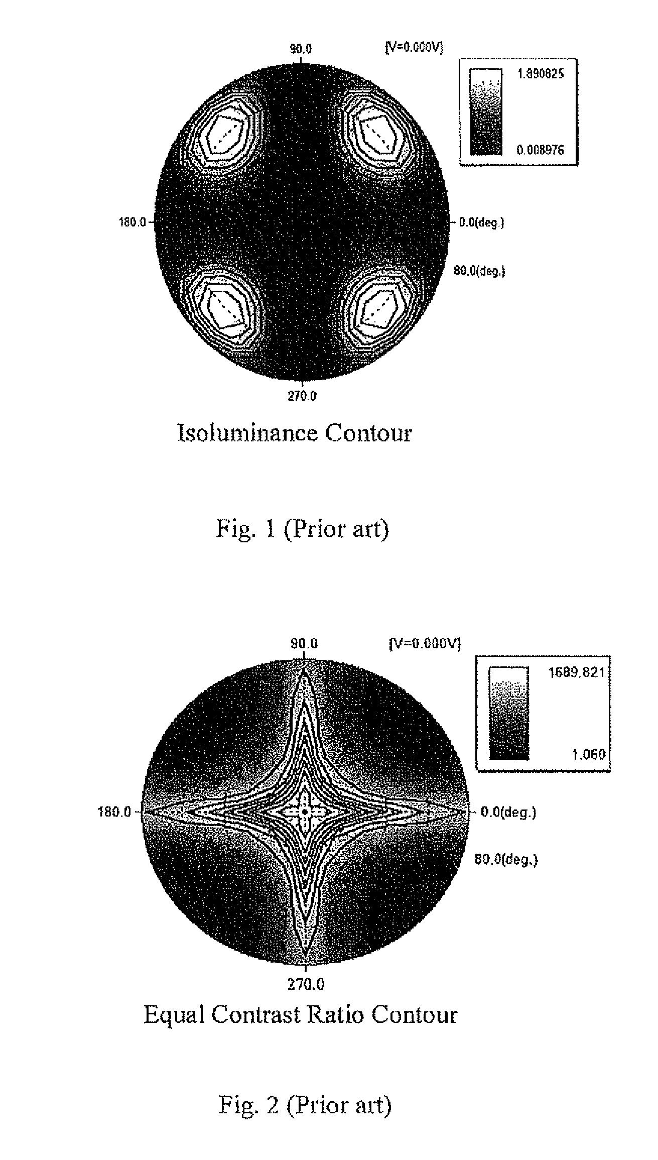
As shown in FIG. 1 and FIG. 2, it is not difficult to understand that, when the prior art A-Plate and C-Plate are adopted, their compensation values result in a severe dark-state light leakage phenomenon at a large viewing angle.
The contrast at a large viewing angle becomes poor, and the range of viewing angle is small.

Method used


Image

  • Liquid crystal display and method of optical compensation thereof
  • Liquid crystal display and method of optical compensation thereof
  • Liquid crystal display and method of optical compensation thereof

Examples


Embodiment Construction

[0055]Spatially relative terms, such as “beneath”, “below”, “lower”, “above”, “upper” and the like, may be used herein for ease of description to describe one element or feature's relationship to another element(s) or feature(s) as illustrated in the figures. It will be understood that the spatially relative terms are intended to encompass different orientations of the device in use or operation in addition to the orientation depicted in the figures.

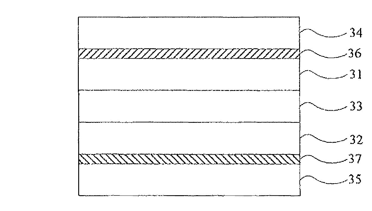
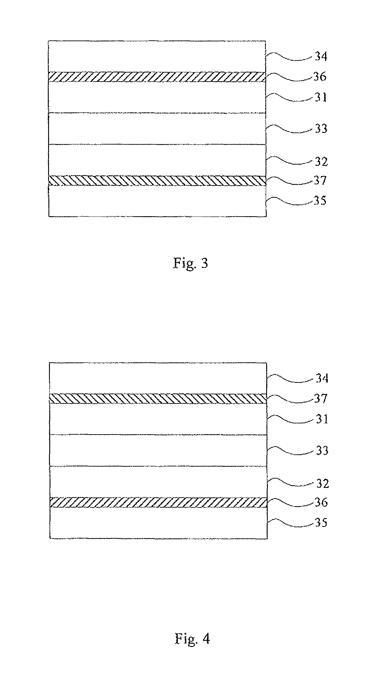
[0056]Please refer to FIG. 3, FIG. 3 is a schematic diagram showing a structure of a liquid crystal display according to a first preferred embodiment of the present invention.

[0057]According to the embodiment of the present invention, the liquid crystal display is preferably a vertical alignment liquid crystal display. In the visible wavelength range (380 nm, 760 nm), preferably, 550 nm, a range of an optical path difference of liquid crystal LCΔND of the liquid crystal display at a wavelength of 550 nm is 324.3 nm≦LCΔND≦342.8 nm, namely...


PUM

PropertyMeasurementUnit
optical path differenceaaaaaaaaaa
thicknessaaaaaaaaaa

Abstract

The present invention discloses a liquid crystal display and a method of optical compensation thereof. Specifically, the present invention adjusts compensation values of a uniaxial positive birefringence A-Plate and a uniaxial negative birefringence C-Plate, especially a value range of retardation in a thickness direction Rth of the uniaxial negative birefringence C-Plate is controlled. By adjusting the compensation values of the above-mentioned two types of compensation films, the dark-state light leakage phenomenon is suppressed. The present invention is capable of suppressing the dark-state light leakage phenomenon at a large viewing angle effectively and increasing the contrast and clarity at a large viewing angle.

Description

BACKGROUND OF THE INVENTION[0001]1. Field of the Invention[0002]The present invention relates to a liquid crystal display technology, more particularly, to a liquid crystal display and a method of optical compensation thereof.[0003]2. Description of the Related Art[0004]With the growing popularity of liquid crystal display panels, the display quality requirements for liquid crystal display panels have become increasingly demanding. Take the thin film transistor liquid crystal display (TFT-LCD) as an example. As the observation angle of the TFT-LCD increases, the contrast of screen gradually decreases and the screen clarity also gradually decreases. This is because the birefringence of the liquid crystal molecules in the liquid crystal layer changes as the observation angle changes. As a result, a wide viewing angle compensation film is utilized to perform compensation so that dark-state light leakage is effectively reduced to greatly improve the contrast of the screen within a certa...

Claims


Application Information

Patent Timeline
Patent Type & Authority Patents(United States)
IPC IPC(8): G02F1/1335G02F1/1337G02F1/13363
CPCG02F1/13363G02F1/133528G02F2001/133631G02F2413/02G02F2413/13G02F2413/14G02F1/133631G02F1/133742
Inventor KANG, CHIHTSUNGHAI, BO
Owner TCL CHINA STAR OPTOELECTRONICS TECH CO LTD
Learn More