Micro-optic viewing arrangement

a micro-optic and viewing arrangement technology, applied in the field of micro-optic viewing arrangement, can solve the problems of destroying the optical effect, micro-optic representation arrangement only providing sharp imaging, and inability to reproduce optically variable elements

Active Publication Date: 2018-08-14
GIESECKE & DEVRIENT CURRENCY TECHNOLOGY GMBH
View PDF44 Cites 0 Cited by
  • Summary
  • Abstract
  • Description
  • Claims
  • Application Information

AI Technical Summary

Benefits of technology

[0014]It is therefore the object of the present invention to avoid the above-stated problems of the prior art and to provide micro-optic viewing arrangements for micro-optic representation arrangements such as for example moiré magnifiers and modulo mapping arrangements, which on their upper sides are equipped with one or several functional coatings, but nevertheless provide sharp imagings of the microstructures to be imaged. Functional coatings are in particular coatings that make possible a bonding, such as coatings that guarantee a protection against soiling and / or scratching.

Problems solved by technology

A special role has been played here for some time by security elements having optically variable elements which convey different pictorial impressions to the viewer from different viewing angles, because optically variable elements cannot be reproduced even with high-quality color copiers.
However, such structures are more and more used also for purposes other than security applications, which is why their value as security features has gone down, because they are often rather perceived as a design feature and receive little attention.
However, micro-optic representation arrangements only provide a sharp imaging, when the microstructures to be imaged are located exactly in the focal plane of the lenses or of the any other microfocusing elements.
An over-coating of the lenses, for example with a dirt-repellent coating, leads to a deterioration and in the worst case to a destruction of the optical effect, because the focal distance (focal length) of the microfocusing elements changes through the over-coating, and thus the microstructures no longer lie exactly in the focal plane of the microfocusing elements: the imaging becomes unsharp or can even completely “disappear”.
A similar problem occurs upon embedding window security threads having micro-optic representation arrangements.
Without bonding the paper bars lying above the thread may easily lift from the thread and can thus be quickly damaged.
In practice, however, it is hardly possible to selectively coat with adhesive only those regions of a security threads that are later hidden under paper bars.
Furthermore, it is hardly possible in practice to selectively leave out given partial regions, such as the window regions of a window security thread, when a bank note is finally equipped with a dirt-repellent coating.

Method used


Image

  • Micro-optic viewing arrangement
  • Micro-optic viewing arrangement
  • Micro-optic viewing arrangement

Examples


Embodiment Construction

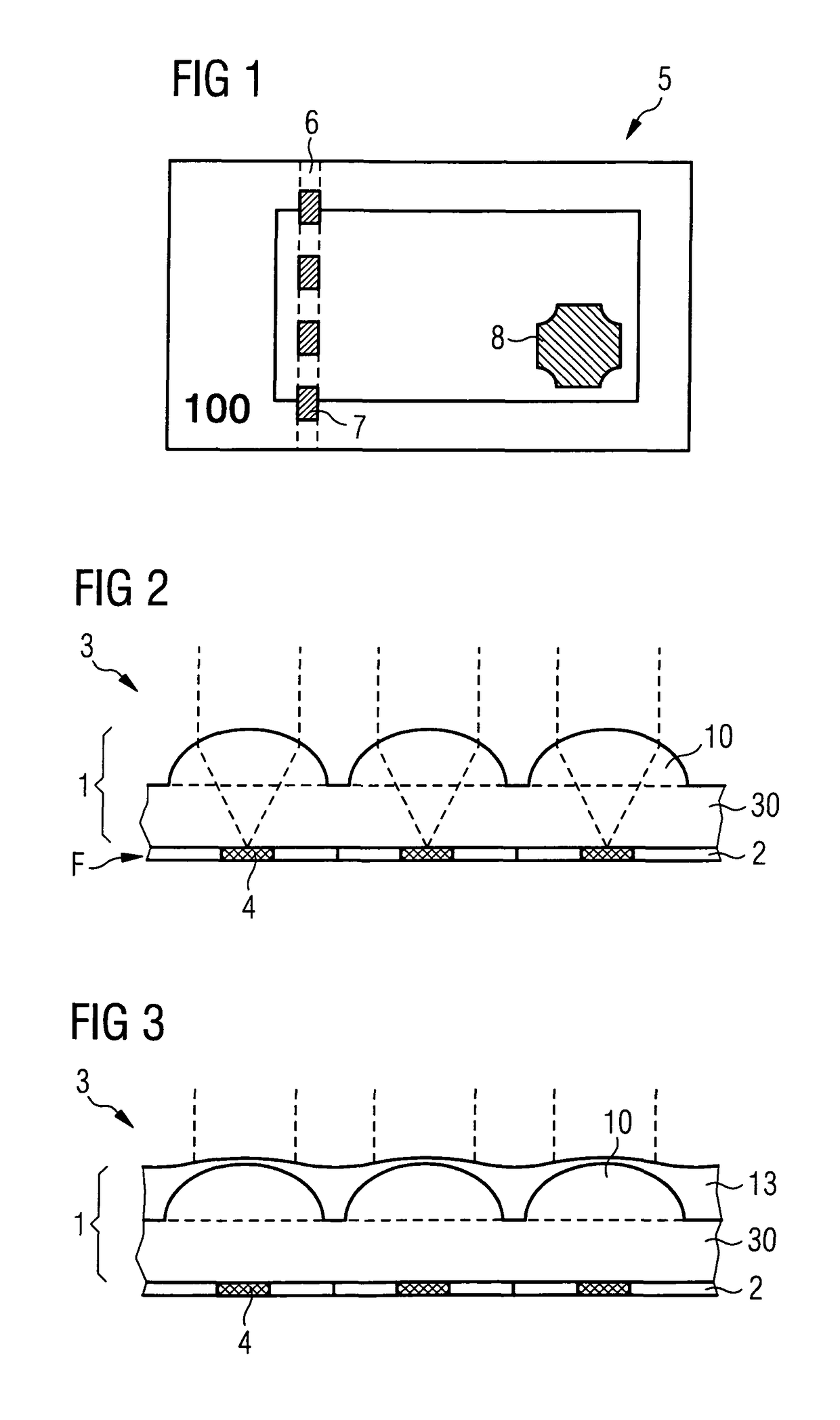
[0079]FIG. 1 shows a schematic depiction of a bank note 5 with two security elements 6 and 8, wherein the security element 6 represents a window security thread, which emerges in window regions 7 of the bank note 5, while it is embedded inside the bank note 5 in the interjacent areas. The security element 8 is a bonded transfer element of any arbitrary form. The security element 8 can also be configured in the form of a cover foil, which is arranged above a window region or through opening of the bank note. The security element can be designed to be viewed in plan view or in transmission, or to be viewed in plan view as well as in transmission. For foil security elements that are to be attached above a through opening also such representation arrangements are very attractive in which on both sides of the microstructure arrangement lens arrangements are provided.

[0080]Both the window security thread 6 and the transfer element 8 can contain micro-optic viewing arrangements of the pres...


PUM

PropertyMeasurementUnit
thicknessesaaaaaaaaaa
diametersaaaaaaaaaa

Abstract

A micro-optical inspection arrangement comprises micro-focusing elements which are composite bodies consisting of a main part and an additional part and which have a reference focal length. The main parts are provided as micro-focusing element preforms, and the additional parts are formed from one or more functional coatings. The invention also relates to a method for producing such a micro-optical inspection arrangement and to a micro-optical displaying arrangement comprising the micro-optical inspection arrangement according to the invention and a microstructure arrangement, in particular a moiré magnification arrangement and a modulo magnification arrangement. The invention also relates to security elements and data carriers that have the micro-optical inspection arrangement according to the invention.

Description

BACKGROUND OF THE INVENTION[0001]The invention relates to a micro-optic viewing arrangement having a multiplicity of microfocusing elements that focus in a target focal-plane and form a viewing grid. The invention also relates to micro-optic representation arrangements that have a micro-optic viewing arrangement according to the invention, security elements for securing the authenticity of data carriers that have a micro-optic viewing arrangement according to the invention, and data carriers that have a micro-optic viewing device according to the invention. The invention furthermore relates to a method for manufacturing the micro-optic viewing arrangement and a method for manufacturing data carriers having the micro-optic viewing arrangement according to the invention.[0002]Data carriers, such as value documents or identification documents, bank notes, deeds, checks, but also other objects of value, such as branded articles, are often provided for safeguarding purposes with security...

Claims


Application Information

Patent Timeline
Patent Type & Authority Patents(United States)
IPC IPC(8): B42D25/00B42D15/00B42D25/342B29D11/00B42D25/40G02B3/00B41M1/24B41M3/14
CPCB42D15/00B29D11/00298B29D11/00365B42D25/00B42D25/40G02B3/0031B42D25/342Y10T29/49982B41M1/24B41M3/148
Inventor HOFFMULLER, WINFRIEDRAHM, MICHAELBURCHARD, THEODORRAUCH, ANDREASSEIDLER, RUDOLFBUCKER, ANNEWEINGARTNER, ARMINWIEDNER, BERNHARDFUHSE, CHRISTIAN
Owner GIESECKE & DEVRIENT CURRENCY TECHNOLOGY GMBH
Why Eureka
Try Eureka