Display device for vehicle

A technology for display devices and vehicles, which is applied to identification devices, vehicle components, static indicators, etc., can solve problems such as poor contrast, difficulty in suppressing visibility, and reduction, and achieve the effect of ensuring visibility

Active Publication Date: 2019-10-08
DENSO CORP
View PDF8 Cites 0 Cited by
  • Summary
  • Abstract
  • Description
  • Claims
  • Application Information

AI Technical Summary

Problems solved by technology

Therefore, regardless of the day and night when the external brightness is different, the captured pixel values ​​constituting the camera image are all the same value or close to the value through the filtering process, so that in the disclosed device of Patent Document 1, the determined background brightness cannot reflect the actual Ambient brightness
As a result, there is a possibility that the contrast of the displayed image with respect to the external scenery is insufficient or the contrast is excessively poor, making it difficult to suppress the decrease in visibility.

Method used


Image

  • Display device for vehicle
  • Display device for vehicle
  • Display device for vehicle

Examples


no. 1 approach

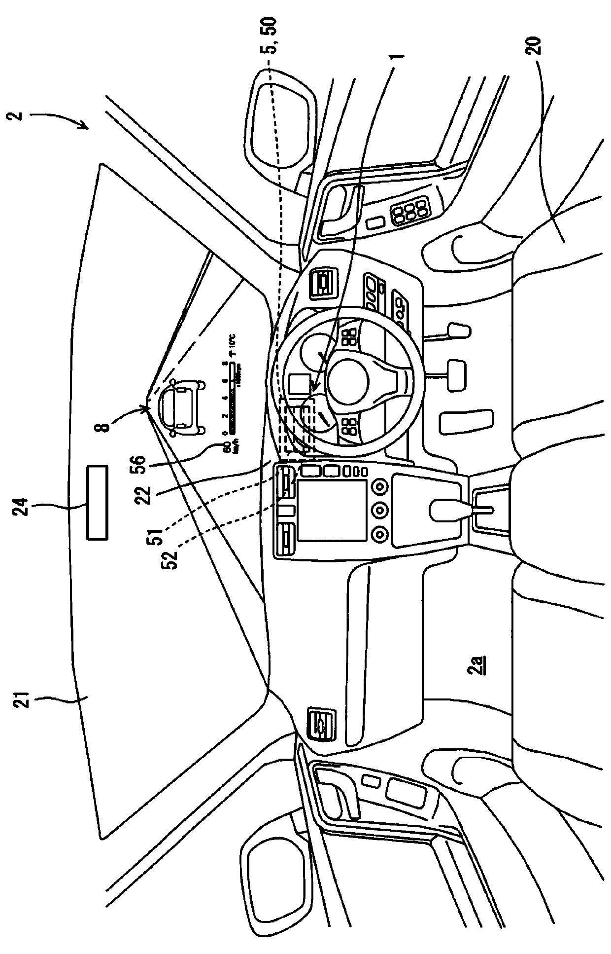
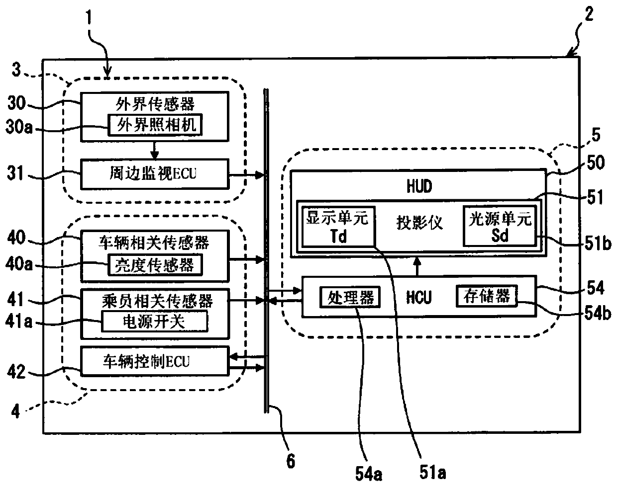
[0042] Such as figure 1 , 2 As shown, the driving assistance system 1 according to the first embodiment of the present disclosure is mounted on a vehicle 2 . The driving assistance system 1 is configured to include a peripheral monitoring system 3 , a vehicle control system 4 , and a vehicle display device 5 . These respective elements 3 , 4 , and 5 are connected to each other via an in-vehicle network 6 such as a LAN (Local Area Network), for example.

[0043] Such as figure 2 As shown, the surrounding monitoring system 3 includes a surrounding sensor 30 and a surrounding monitoring ECU (Electronic Control Unit: Electronic Control Unit) 31 . The surrounding sensor 30, for example, detects obstacles such as other vehicles that may collide outside the vehicle 2, artificial structures, people, and animals, and speed signs and various types of signs existing outside the vehicle 2 (that is, outside the compartment 2a). Traffic signs such as warning signs, etc. The peripheral...

no. 2 approach

[0075] The second embodiment of the present disclosure is a modified example of the first embodiment. Such as Figure 11 As shown, in S103 of the display control flow according to the second embodiment, in S2103b following S103a, the captured pixel values ​​Tc of the pixels of the plurality of pixel portions constituting the specific pixel portion Pc are compared by color. Thus, in S2103b, as Figure 12 The captured pixel values ​​Tc of the same value or within the same range are extracted by color from the most pixel portion Pcm in which the number of pixels giving the captured pixel values ​​Tc of the same value or within the same range is the largest. here, Figure 12 The maximum pixel portion Pcm having the largest number of pixels given the captured pixel value Tc of the same value is shown. On the other hand, although not shown, the captured pixel value Tc in the same range refers to each captured pixel value of a specific pixel portion Pc in a plurality of ranges div...

no. 3 approach

[0080] The third embodiment of the present disclosure is a modified example of the first embodiment. Such as Figure 13 As shown, in S103 of the display control flow according to the third embodiment, S3103a and S3103b are executed.

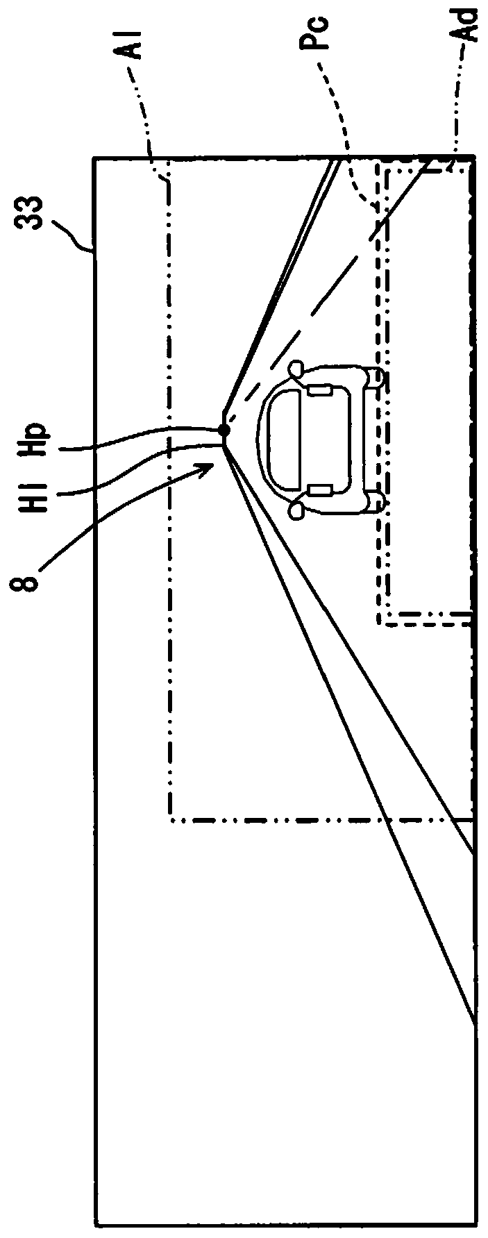
[0081] First in S3103a, select Figure 14 In the camera image 33 shown, a single pixel portion captured at a position limited to the external scenery 8 on the front side of at least one of the vanishing point Hp and the horizon H1 and overlapping the display area Ad is defined as the specific pixel portion Pc. At this time, in the third embodiment, it will be as Figure 14 A fixed single pixel portion set in advance as such is selected as the specific pixel portion Pc. In addition, at this time, in the third embodiment, the captured pixel values ​​Tc of individual pixel portions constituting the selected specific pixel portion Pc are extracted for each color and stored in the memory 54b. In addition, a single pixel portion as a specific pixel...


PUM


Abstract

This display device for vehicle provides virtual display of a display image which is visible in a visible area (7) within a cabin (2a), by projecting a display image (56) on a projection member (21) which allows the passage of the outside scenery therethrough, in a vehicle (2) fitted with an outside camera (30a) which acquires a camera image (33) by capturing the outside scenery (8), and a brightness sensor (40a) which detects the outside brightness (Lo) of the outside scenery. The display device for vehicle comprises: a head-up display (50) which forms a display image by emitting light; a memory (54b) which stores, as correction data (Dr), the correlation of the corrected pixel values (Tr) converted by correction according to the outside brightness from the captured pixel values (Tc) which constitute the camera image, with the captured pixel values; conversion blocks (S104, S2104, S3104, S4104, S5104) which, on the basis of correction data stored in the memory, convert the captured pixel values of a specific pixel portion (Pc) which have captured the front side of the vanishing point and / or the horizon from among camera images captured by the outside camera, to corrected pixel values according to the outside brightness detected by a brightness sensor; and display control blocks (S105, S5105, S6105, S7105) which control virtual image display brightness (Ld) of the display imageprovided by the head-up display so as to correspond to the corrected pixel values converted from the captured pixel values by the conversion blocks.

Description

[0001] Cross References to Related Applications [0002] This application claims the priority of Japanese Patent Application No. 2017-31370 filed on February 22, 2017, the entire contents of which are incorporated herein. technical field [0003] The present disclosure relates to a vehicular display device that projects a display image on a projection member that sees through an external scenery, thereby virtual-displaying the display image so that it can be visually recognized in a visual recognition area in a vehicle interior. Background technique [0004] Conventionally, there is known a display device for a vehicle that emits light from a display image projected onto a projection member by a head-up display (HUD: Head Up Display). [0005] In the device disclosed in Patent Document 1 as one of such vehicle display devices, the external scenery serving as the background of the displayed image is photographed by an external camera, and the camera image is acquired in such ...

Claims


Application Information

Patent Timeline
Patent Type & Authority Applications(China)
IPC IPC(8): B60K35/00B60R11/02G02B27/01G09G5/00G09G5/10G09G5/36
CPCB60K35/00G02B27/01G09G5/10G09F21/049G09F27/005B60K2370/1529B60K2370/349G09G2360/144G09G2320/066G09G2380/10G02B2027/014G02B2027/0138G02B2027/0112G02B2027/0118H04N23/63H04N23/90B60R11/02G09F9/00G09G5/36
Inventor 成濑洋一
Owner DENSO CORP
Why Eureka
Try Eureka