3D time-of-light camera and method

a time-of-light camera and time-offlight technology, applied in the field of 3d time-of-light cameras, can solve the problems of inability to acquire all raw images instantaneously, current tof cameras and methods cannot deliver optimal depth maps for moving sceneries, and the temporal delay between raw data acquisitions, so as to achieve the effect of effectively detecting and compensating motion artifacts without requiring high computational efforts or complex additional hardwar

Active Publication Date: 2015-11-24
SONY CORP
View PDF0 Cites 9 Cited by
  • Summary
  • Abstract
  • Description
  • Claims
  • Application Information

AI Technical Summary

Benefits of technology

[0010]It is an object of the present invention to provide a 3D time-of-flight camera and a corresponding 3D time-of-flight method which effectively detect and compensate motion artifacts without requiring high computational efforts or complex additional hardware. It is a further object of the present invention to provide a processor and a corresponding processing method as well as a corresponding computer program for implementing said processing method and a computer readable non-transitory medium.
[0023]The present invention is based on the idea to detect motion artifacts and, in a preferred embodiment, compensate them by utilizing raw values (i.e. sample values) of a prior acquisition (i.e. a previous set of samples) of said raw values. The basic assumption is that raw values acquired by ToF devices, i.e. the detector, vary smoothly over time. Strong artifacts are caused by rapid changes of scene features or laterally moving edges, e.g. depth- and / or color-edges. Such moving edges include, for instance, moving edges of non-modulated radiation (including background light). Today's cameras assume the unknowns (phase, amplitude, background light / non-modulated light) to vary smoothly. Moving objects can cause discontinuities of one or multiple unknowns (e.g. edges of depth, color, or non-modulated light).

Problems solved by technology

There are several reasons, why current ToF cameras and methods do not deliver optimal depth maps for moving sceneries.
Another reason is the temporal delay between raw data acquisitions.
Current ToF cameras are not able to acquire all raw images instantaneously, but have to capture them consecutively.
If one or multiple of the unknowns (depth, background light, reflectivity) change during that process, the reconstruction generates incorrect results.
These kinds of errors might be caused, for instance, by rapidly changing features of the scene, for instance by moving depth or color edges.
If the movement is parallel to the projection beam of a certain pixel, the signal deviations affecting this pixel are small due to the typically low speed of the objects.
In contrast, laterally moving edges effect rapid changes of raw values, thus leading to strong errors and strong motion artifacts.
The drawback of this approach is, however, the high computational effort, which necessitates means like GPU implementations to process the data with appropriate speed.
Further drawbacks are the necessity for intensity normalization of different raw channels and that there is no dense reconstruction (necessity for inpainting).

Method used


Image

  • 3D time-of-light camera and method
  • 3D time-of-light camera and method
  • 3D time-of-light camera and method

Examples


Embodiment Construction

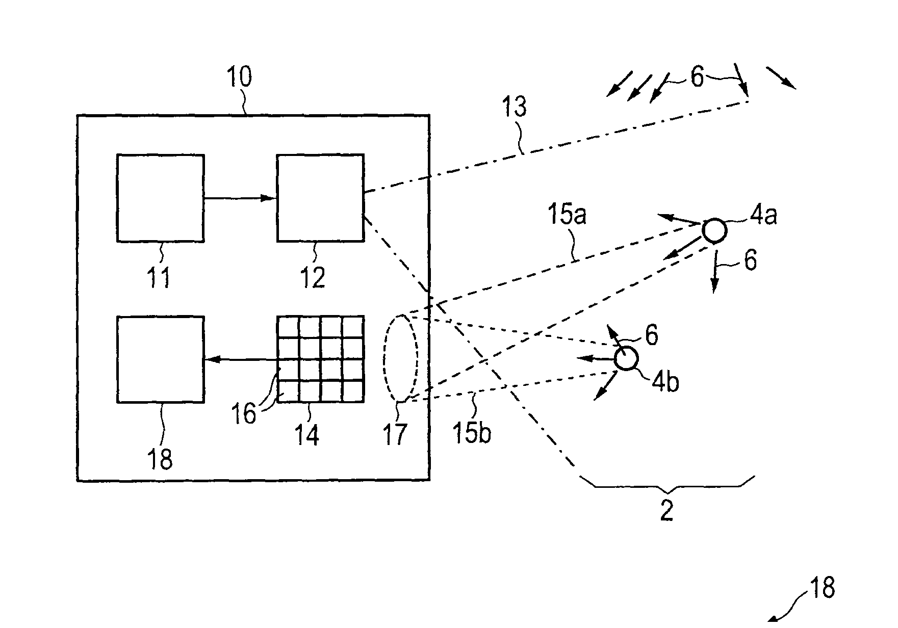
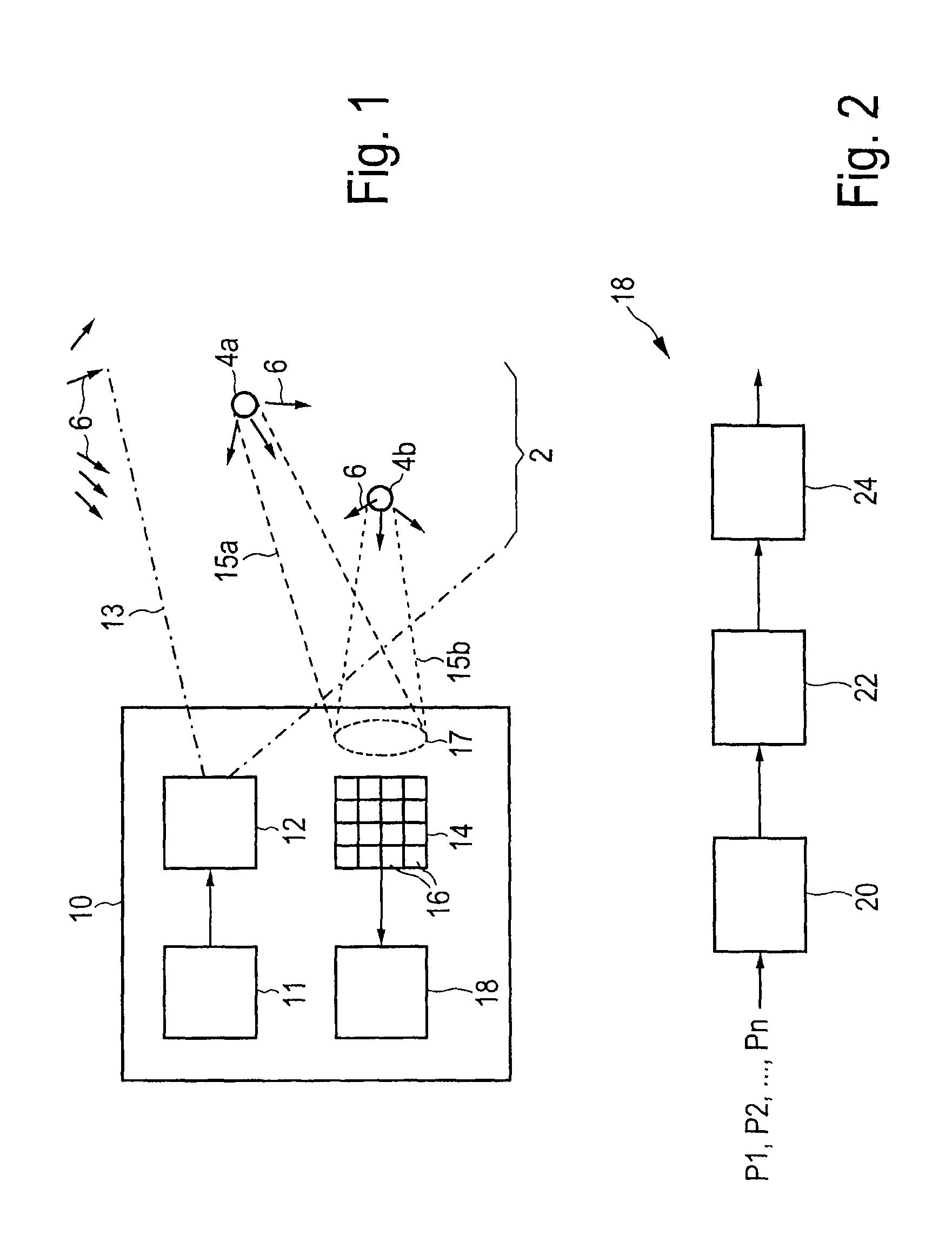
[0042]A schematic diagram of a 3D ToF camera 10 according to the present invention is shown in FIG. 1. Such a camera 10 is generally used for acquiring information about a scene 2. Such information may particularly comprise information for generating depth images of a scene, information about phase shifts of a scene or environmental information about the scene. The following description referring to FIGS. 1 to 6 will, as an example, focus on the acquisition of depth images, in particular on the acquisition of distance information about the distance of one or more objects, in the embodiment shown in FIG. 1 a background object 4a and a foreground object 4b, of the scene 2 from the camera 10. This distance information is, besides the reflectivity of one or more objects 4 of the scene 2 and the intensity of non-modulated radiation (which includes ambient light and non-modulated light emitted by the radiation source) 6, one of the three unknown factors to be determined to be able to gene...


PUM


Abstract

The present invention relates to a 3D time-of-flight camera for acquiring information about a scene, in particular for acquiring depth images of a scene, information about phase shifts of a scene or environmental information about the scene. The proposed camera particularly compensates motion artifacts by real-time identification of affected pixels and, preferably, corrects its data before actually calculating the desired scene-related information values from the raw data values obtained from radiation reflected by the scene.

Description

CROSS-REFERENCE TO RELATED APPLICATIONS[0001]The present application claims priority of European patent application 10188353.6 filed on Oct. 21, 2010.FIELD OF THE INVENTION[0002]The present invention relates to a 3D time-of-flight camera and a corresponding 3D time-of-flight method for acquiring information about a scene, in particular for acquiring depth images of a scene, information about phase shifts between a reference signal and incident radiation of a scene or environmental information about the scene. Further, the present invention relates to a processor and a corresponding processing method for use in such a 3D time-of-flight camera and method. Still further, the present invention relates to a computer program for implementing such a processing method on a computer and a computer readable non-transitory medium storing such a computer program.BACKGROUND OF THE INVENTION[0003]3D time-of-flight (ToF) cameras acquire depth images by determining the time which radiation, prefera...

Claims


Application Information

Patent Timeline
Patent Type & Authority Patents(United States)
IPC IPC(8): H04N13/00G01S17/89G01S17/894
CPCG01S17/89G01S17/894
Inventor SCHMIDT, MIRKOZIMMERMANN, KLAUS
Owner SONY CORP
Why Eureka
Try Eureka