
Adaptable resonator filter

a resonator filter and adaptable technology, applied in the field of filters, can solve the problems of small losses caused by such resonator filters and adaption errors at the end of the adjustment area

Active Publication Date: 2015-11-24
INTEL CORP
View PDF13 Cites 1 Cited by
  • Summary
  • Abstract
  • Description
  • Claims
  • Application Information

AI Technical Summary

Benefits of technology

This solution enables precise correction of the resonator filter's adaptation during use, ensuring optimal impedance matching and reduced reflection coefficients across a wide frequency range, thereby meeting the requirements of systems like LTE standards.

Problems solved by technology

This is due to the fact that losses caused by such resonator filters are small, which means only a slight damping of the effective signal.
This leads to a situation where adaption errors occur in the ends of the adjustment area.

Method used


Image

  • Adaptable resonator filter
  • Adaptable resonator filter
  • Adaptable resonator filter

Examples


Embodiment Construction

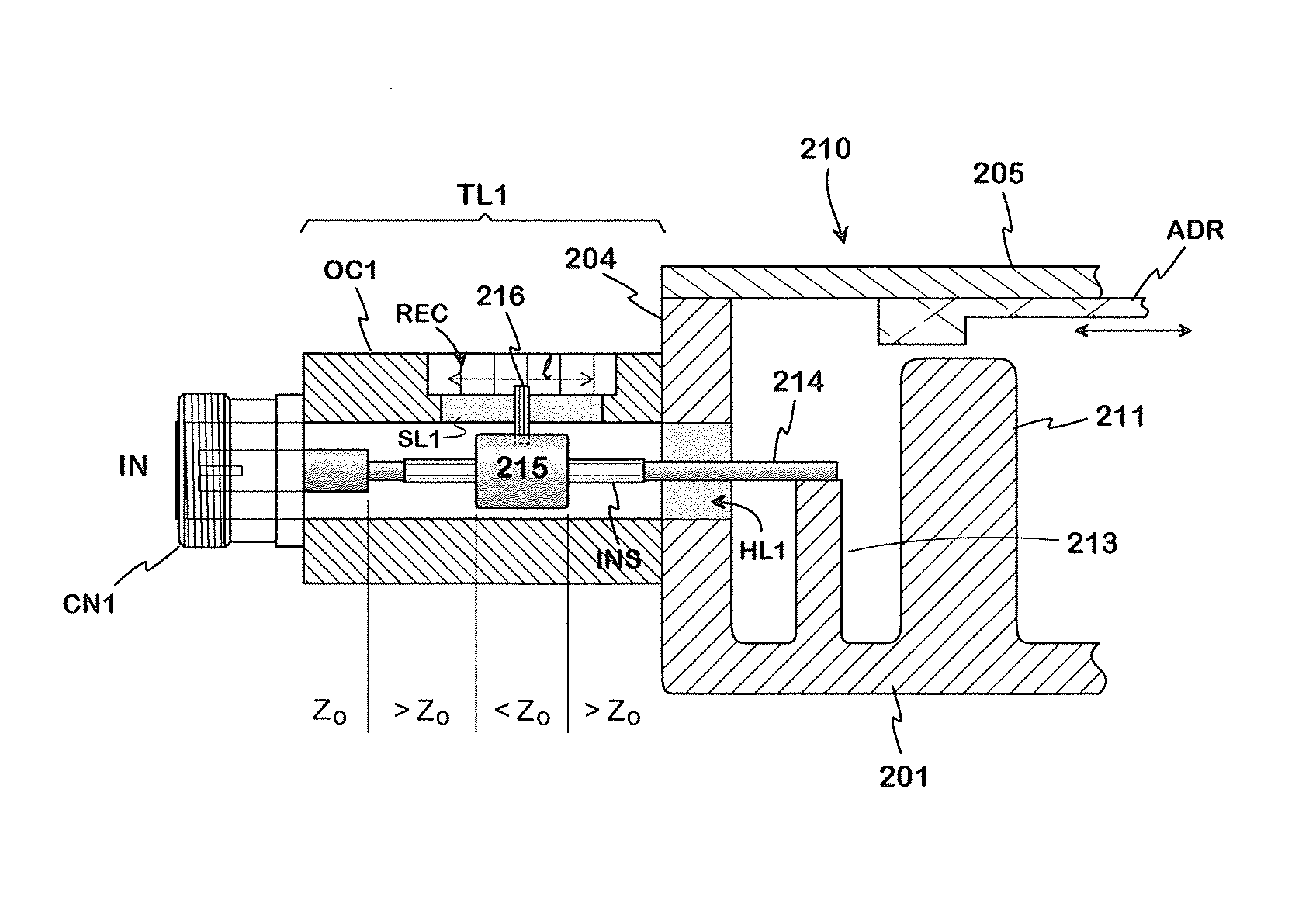
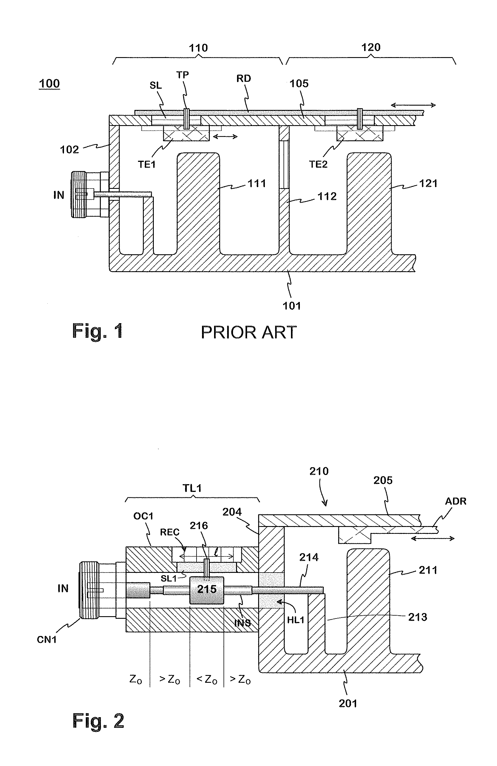
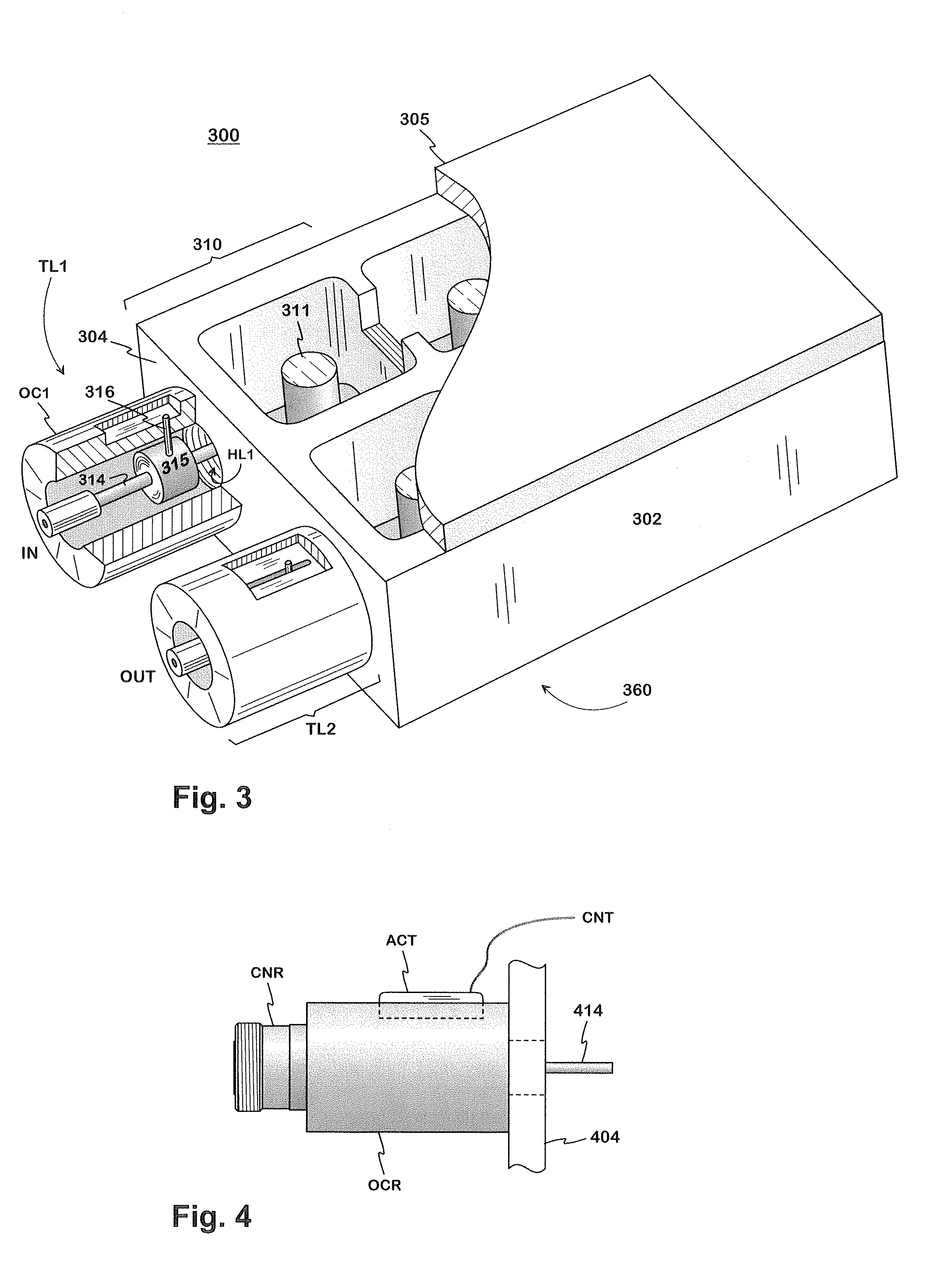
[0016]FIG. 1 was already described in connection with the description of prior art. FIG. 2 shows an example of the adaptation arrangement on the input side in a resonator filter according to the invention. The drawing is a vertical cross-section, and it shows a coaxial input connector CN1, a coaxial transfer line TL1 and an input resonator 210. The adjustment piece ADR under the lid 205, which piece moves the pass band of the filter, is also marked in the figure. There can be a separate actuator for moving the adjustment piece, which actuator together with the adjustment piece makes up the adjustment apparatus of the pass band. The transfer line is part of the transfer path of the filter, in such a way that its outer conductor OC1 is connected in a galvanic manner by its one end to the outer conductor of the input connector CN1 and by its other end to the end wall 204 of the filter casing, and the middle conductor is connected by its starting end to the middle conductor of the input...


PUM


Abstract

An adaptable filter made up of cavity resonators. The adaptation takes place by adjusting the connection from the input connector (CN1) of the filter to the input resonator and from the output resonator to the output connector. For adjusting the connection there is a coaxial transfer line (TL1), the outer conductor (OC1) of which is connected by its one end to the wall of the filter casing and by its other end to the outer conductor of the connector (CN1) and the inner conductor of which extends from the middle conductor of the connector to the cavity of the resonator and there into the internal connecting member of the resonator. A middle rod belonging to the inner conductor is surrounded over a certain distance by a cylindrical conductive tuning element, which can be moved by sliding it along the middle rod.

Description

BACKGROUND OF THE INVENTION[0001]The invention relates to a filter composed of cavity resonators, the adaptation of which filter can be adjusted during use. A typical application of the invention is an antenna filter of a base station of some mobile network.[0002]Cavity resonators are generally used in communications networks for making filters, especially when the effect of the signal to be transferred is relatively large. This is due to the fact that losses caused by such resonator filters are small, which means only a slight damping of the effective signal. Additionally their response characteristics are easy to control and adjust even according to strict specifications.[0003]In most filters, both the center frequency and bandwidth of the pass band of the filter is meant to be fixed. In some filters the bandwidth of the pass band of the filter is meant to be fixed, but the center frequency of the pass band can be made adjustable within range of center frequencies. Thus an adjustm...

Claims


Application Information

Patent Timeline
Patent Type & Authority Patents(United States)
IPC IPC(8): H01P1/20H01P7/04H01P3/06H01P1/205H01P5/04
CPCH01P1/2053H01P5/04
Inventor PARI, PETRIPUOSKARI, JUKKA
Owner INTEL CORP
Learn More