Slotted bobbin magnetic component devices and methods

a magnetic component and bobbin technology, applied in the field of magnetic components, can solve the problems of unintentional misalignment or falling out of the planar winding, insufficient complex magnetic field interactions between the primary and secondary windings, and insufficient conventional winding configurations using conductive wires wound around the bobbin. achieve the effect of improving the use of the winding area, increasing power loss, and increasing power level

Active Publication Date: 2015-12-01
BEL POWER SOLUTIONS INC
View PDF18 Cites 6 Cited by
  • Summary
  • Abstract
  • Description
  • Claims
  • Application Information

AI Technical Summary

Benefits of technology

[0012]The magnetic component of the present invention includes a bobbin for positioning one or more conductive windings or coils. The bobbin includes an elongated bobbin tube extending axially along a bobbin axis of elongation. An axial passage is defined inside the bobbin tube along the axis of elongation. One or more magnetically permeable core members may be placed at least partially into the axial passage. One or more slots are defined in the bobbin tube in at least one plane oriented substantially transverse to the axis of elongation of the bobbin tube. A substantially planar or flat conductive winding insert, or winding sheet, is radially installed onto the bobbin tube at the axial location of the transverse slot. A radial winding insert opening defined in the winding insert allows the winding insert to be installed onto the bobbin tube from the radial direction. One or more detent features are located on the winding insert to prevent inadvertent movement of the winding insert relative to the bobbin.
[0016]In some embodiments, it is an object of the present invention to provide a winding in multiple sections on a bobbin for improved use of the winding area.
[0017]A further object of the present invention is to provide a magnetic component with increased power level without increasing power losses caused by increased proximity effects.
[0020]A further object of the present invention is to provide a winding insert and bobbin having an angular stop to prevent angular movement of the winding insert relative to the bobbin.

Problems solved by technology

One problem with conventional bobbin-wound magnetic components such as transformers that utilize multiple windings is proper positioning of the various coils.
However, in many applications, complex magnetic field interactions are desired among the primary and secondary windings.
Conventional winding configurations using conductive wires wound around a bobbin may be inadequate for such complex field interactions due in part to problems with wire positioning, wire size, etc.
Another problem associated with conventional magnetic component devices includes movement of planar windings during positioning of one or more wire coils on the bobbin structure between the planar windings.
The planar windings may become unintentionally misaligned or may fall out during the coil winding process.
Additionally, coil placement between planar windings may cause the planar windings to flex or bow axially, resulting in uneven coil placement.

Method used


Image

  • Slotted bobbin magnetic component devices and methods
  • Slotted bobbin magnetic component devices and methods
  • Slotted bobbin magnetic component devices and methods

Examples


Embodiment Construction

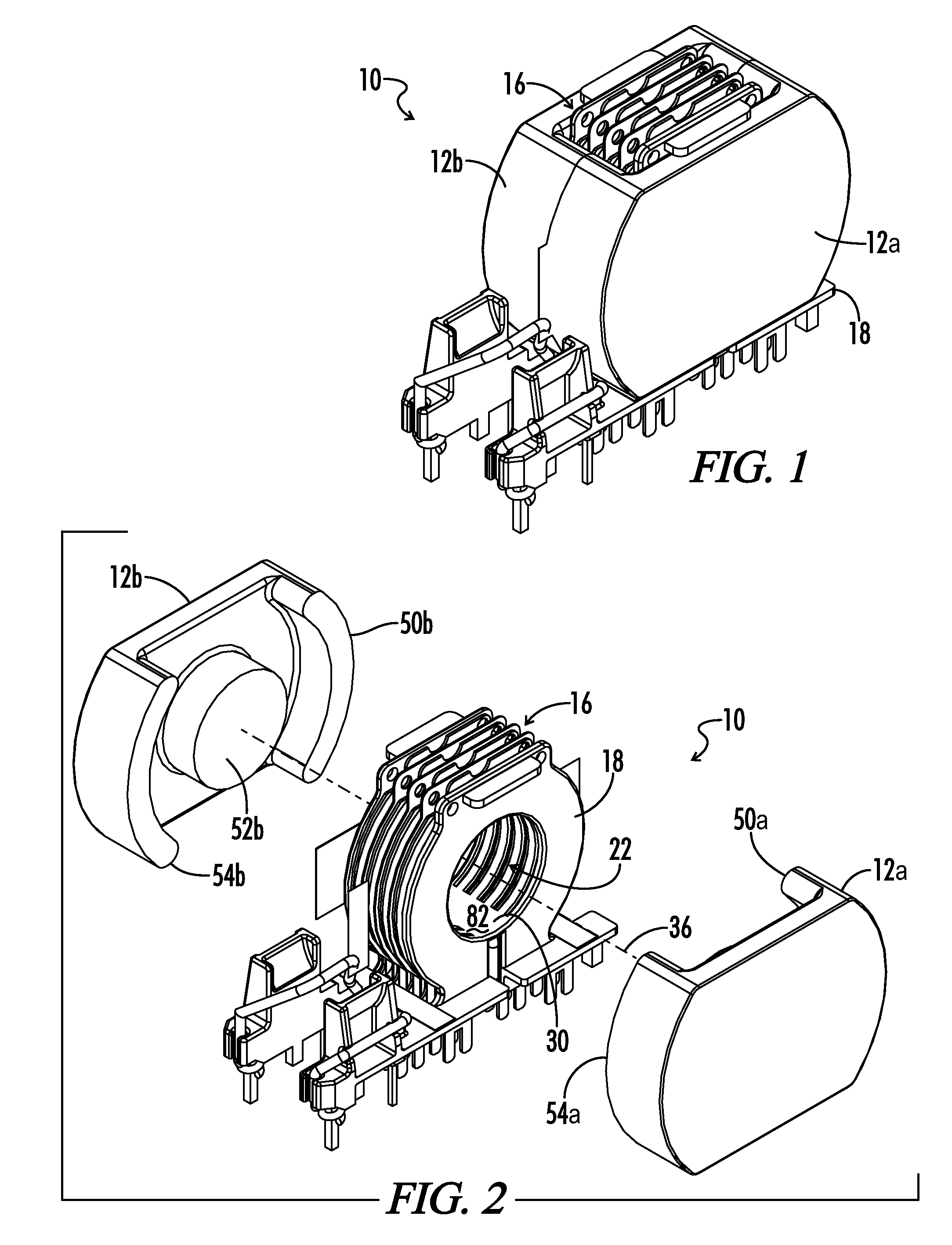
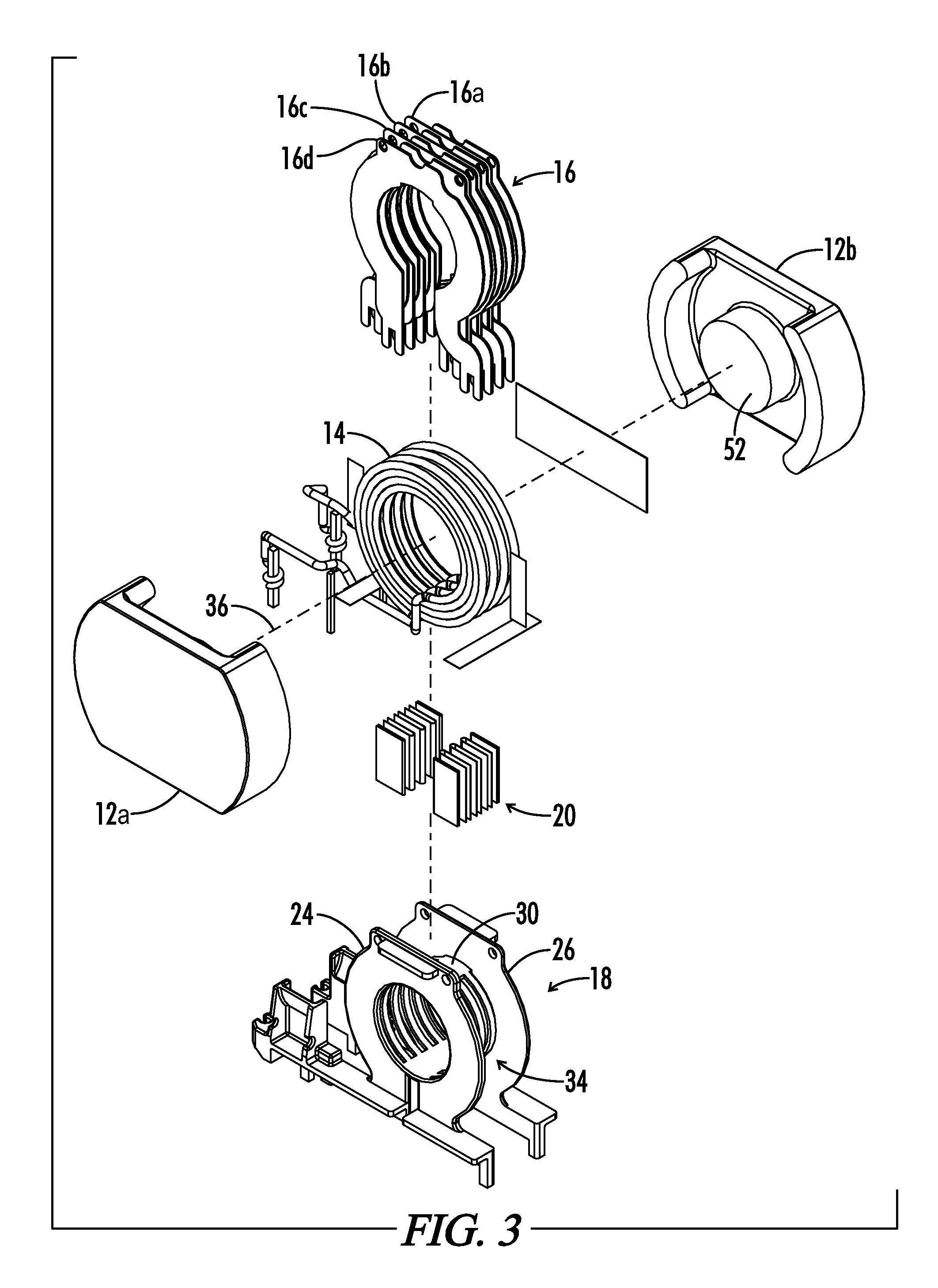
[0048]Referring now to the drawings, FIG. 1 illustrates an embodiment of a magnetic component 10 in accordance with the present invention. Magnetic component 10 includes a bobbin 18 supporting first and second magnetic core halves 12a, 12b. The core halves 12a, 12b, may include any conventional type of suitable core such as a standard or modified E-core, EFD core, EVD core, or an I-core in various embodiments.

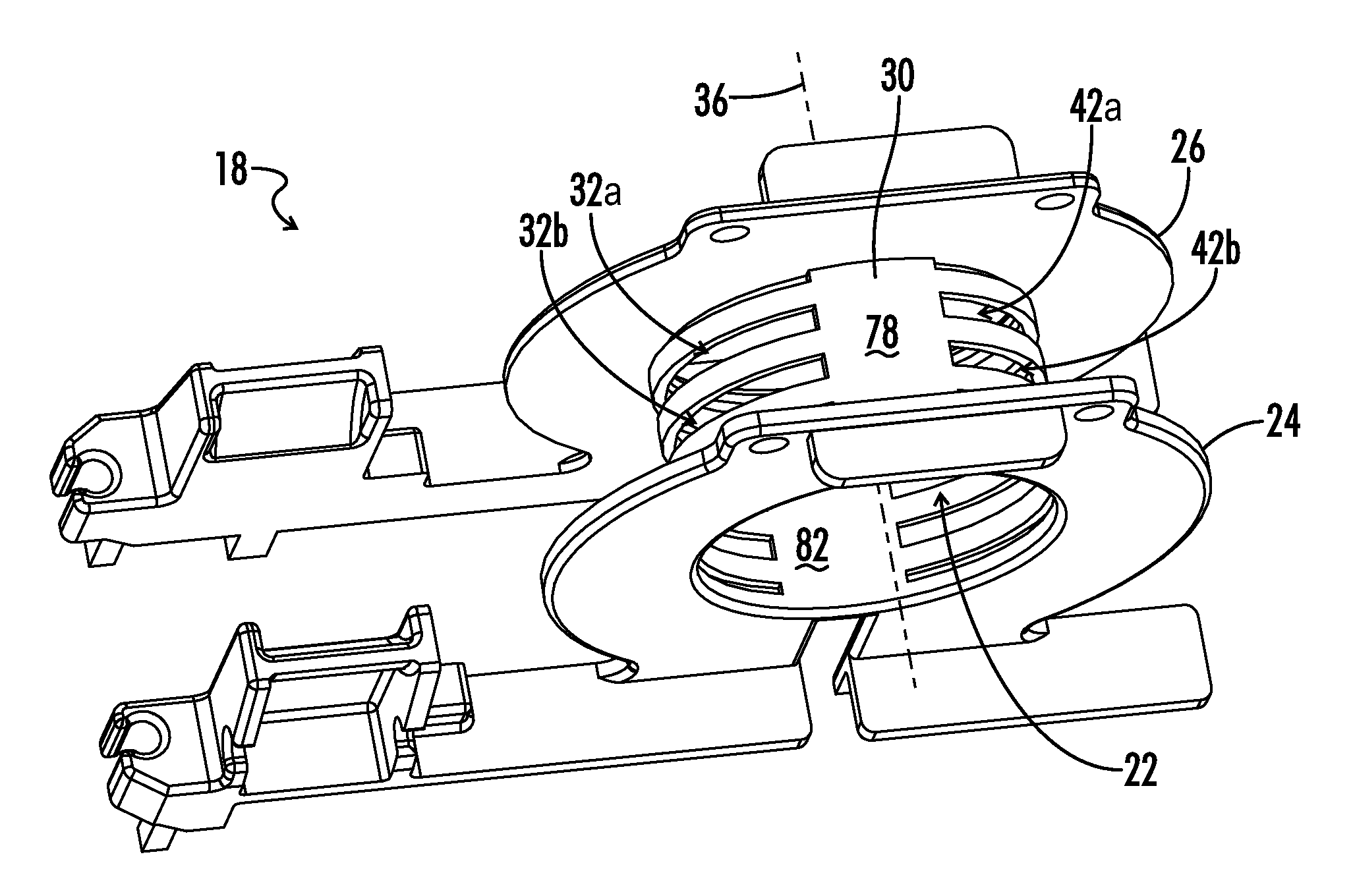
[0049]Bobbin 18 includes an elongated bobbin tube 30 extending along an axis of elongation 36, seen in FIG. 5 and FIG. 9. Bobbin tube 30 generally includes an annular shape such that an axial passage 22 is defined along the axis of elongation. Bobbin tube 30 includes a substantially circular cross-sectional shape in some embodiments. In other embodiments, bobbin tube 30 includes other suitable non-circular cross-sectional shapes such as rectangular, or other curvilinear or polygonal shapes. Each core half 12 includes a middle core leg 52 shaped to be partially received in axial...


PUM

PropertyMeasurementUnit
widthaaaaaaaaaa
gap widthaaaaaaaaaa
conductiveaaaaaaaaaa

Abstract

A slotted bobbin magnetic component device includes a bobbin having an elongated bobbin tube with transverse slots. One or more substantially flat electrically conductive winding inserts are inserted radially onto the bobbin tube via the transverse slots. At least one detent positioned on the winding insert secures the winding insert on the bobbin and prevents the winding insert from becoming misplaced relative to the bobbin. One or more flanges protruding from the bobbin engage one or more corresponding recesses on the winding insert to prevent angular movement of the winding insert relative to the bobbin. One or more primary conductive winding coils are disposed about the bobbin in the gaps between adjacent winding inserts, the coils being formed by axially winding numerous layers over each other in alternating axial winding directions.

Description

CROSS-REFERENCES TO RELATED APPLICATIONS[0001]This application claims benefit of the following patent application(s) which are hereby incorporated by reference: U.S. Provisional Patent Application Ser. No. 61 / 555,361 filed Nov. 3, 2011 and titled “Intersected Transformer”; and co-pending U.S. patent application Ser. No. 13 / 699,060 filed Nov. 5, 2012 and titled “Slotted Bobbin Magnetic Component Devices and Methods,” all of which are hereby incorporated by reference in their entireties.[0002]A portion of the disclosure of this patent document contains material that is subject to copyright protection. The copyright owner has no objection to the reproduction of the patent document or the patent disclosure, as it appears in the U.S. Patent and Trademark Office patent file or records, but otherwise reserves all copyright rights whatsoever.STATEMENT REGARDING FEDERALLY SPONSORED RESEARCH OR DEVELOPMENT[0003]Not ApplicableREFERENCE TO SEQUENCE LISTING OR COMPUTER PROGRAM LISTING APPENDIX[0...

Claims


Application Information

Patent Timeline
Patent Type & Authority Patents(United States)
IPC IPC(8): H01F27/30H01F5/02H01F27/32
CPCH01F27/325H01F5/02H01F27/303
Inventor WILD, URS
Owner BEL POWER SOLUTIONS INC
Why Eureka
Try Eureka