Unlock instant, AI-driven research and patent intelligence for your innovation.

Stress measurement sensor

a stress measurement and sensor technology, applied in the direction of instruments, using electrical/magnetic means, electric/magnetic measurement arrangements, etc., can solve the problems of temporally limited reliable service life of stress measurement sensors formed with such a joining material, measurement errors, etc., and achieve good transmission of arising stresses and good durability

Active Publication Date: 2015-12-08
HORST SIEDLE GMBH & CO KG
View PDF12 Cites 0 Cited by
  • Summary
  • Abstract
  • Description
  • Claims
  • Application Information

AI Technical Summary

Benefits of technology

The patent text discusses the use of glass solder as a joining material for stress measurement sensors. Compared to organic adhesives, glass solder has several advantages such as a simplified manufacturing process and better durability. The text also mentions that the thermal expansion coefficient of glass solder should match that of the material of the base to ensure accurate stress measurements. The inventors found that steel, especially austenitic and duplex steels, was suitable for the base material as it exhibits good transmission of stresses and durability. The text concludes that the technical effects of the patent text are improved accuracy and durability of stress measurement sensors using glass solder and steel as the joining material.

Problems solved by technology

However, the bonding of such foreign substances on the sensor surface, in turn, leads to a change in the running characteristics of the surface acoustic waves, thereby falsifying, or modifying, respectively, the measurement result of the sensor, and leads to measuring errors.
In addition, resin-based compounds do not extend into the temperature ranges required for the use of appropriate stress measurement sensors in certain cases in terms of their temperature resistance, which may include use at 400° C. or more.
In addition, resin-based, and other, organic adhesive compounds of the known type tend to age, so that the reliable service life of a stress measurement sensor formed with such a joining material is temporally limited.
A further known problem associated with a resin-based or organic joining agent is so-called “creep”.
For the sensor, the result of this effect is that a stress that is exerted over an extended period of time is eventually dissipated in the joining agent, in that the joining agent expands, so that the measured value of the sensor element erroneously drifts to the value of the relaxed state under these circumstances.
Finally, in the case of known joining methods, there is frequently a problem that a portion of the stresses, or deformations, respectively, exerted on the base are not transferred into the sensor element, but instead are cushioned by a deformation of the layer of joining material, since that material is not hard enough.
This also leads to a measurement error in the known stress measurement sensors, or at least to a greatly reduced stress sensitivity of the sensor, as compared to sensors having harder joining materials.
This is because when organic adhesives are used, chemical processes occur that are time-limited, which elicits a time-critical moment.
When conducting trials with different material combinations of different starting materials for the base, for the sensor element, more precisely for the carrier crystal thereof, thus for what is typically a piezoelectric crystal, and for the glass solder, the inventors have determined that it is not possible to obtain good results in terms of the joint stability and sensory properties with just any combination of possible materials for the components.
In the case of some combinations of different materials for the aforementioned components, no usable stress measurement sensors using the glass solder as a joining material could be produced.
In the case of such sample experiments, for which the material combinations fail to fulfill the above specified conditions, further investigation revealed that the joints had insufficient shear resistance.
Having insufficient shear resistance, stress measurement sensors manufactured in such a way were no longer suited for practical use, at least not in the required scope.
In particularly extreme cases, cracks were already visible in the glass solder after completing the joining processes, which result in a non-reproducible measurement characteristic of the sensor.
The results produced by ferritic and martensitic steels were clearly less favorable, and thus not preferred.
Tests have shown that process temperatures selected during this process step that exceed 500° C. may result in damage to the surface structure of the sensor element and thereby to an impairment, or even failure, of the sensor function of the sensor element operating according to the SAW principle.

Method used


Image

  • Stress measurement sensor
  • Stress measurement sensor
  • Stress measurement sensor

Examples


Embodiment Construction

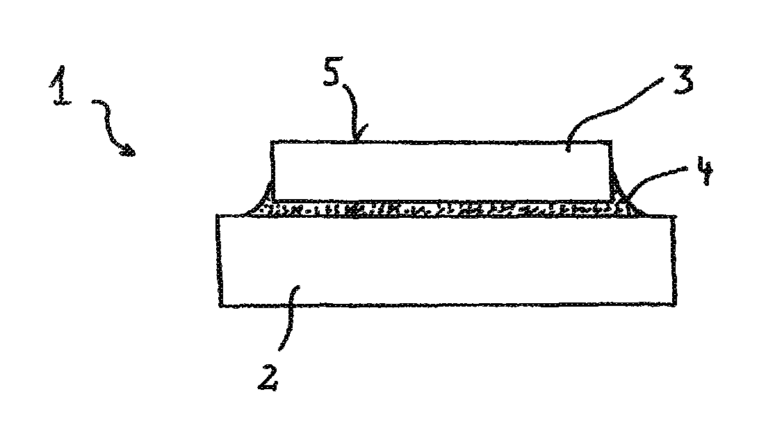
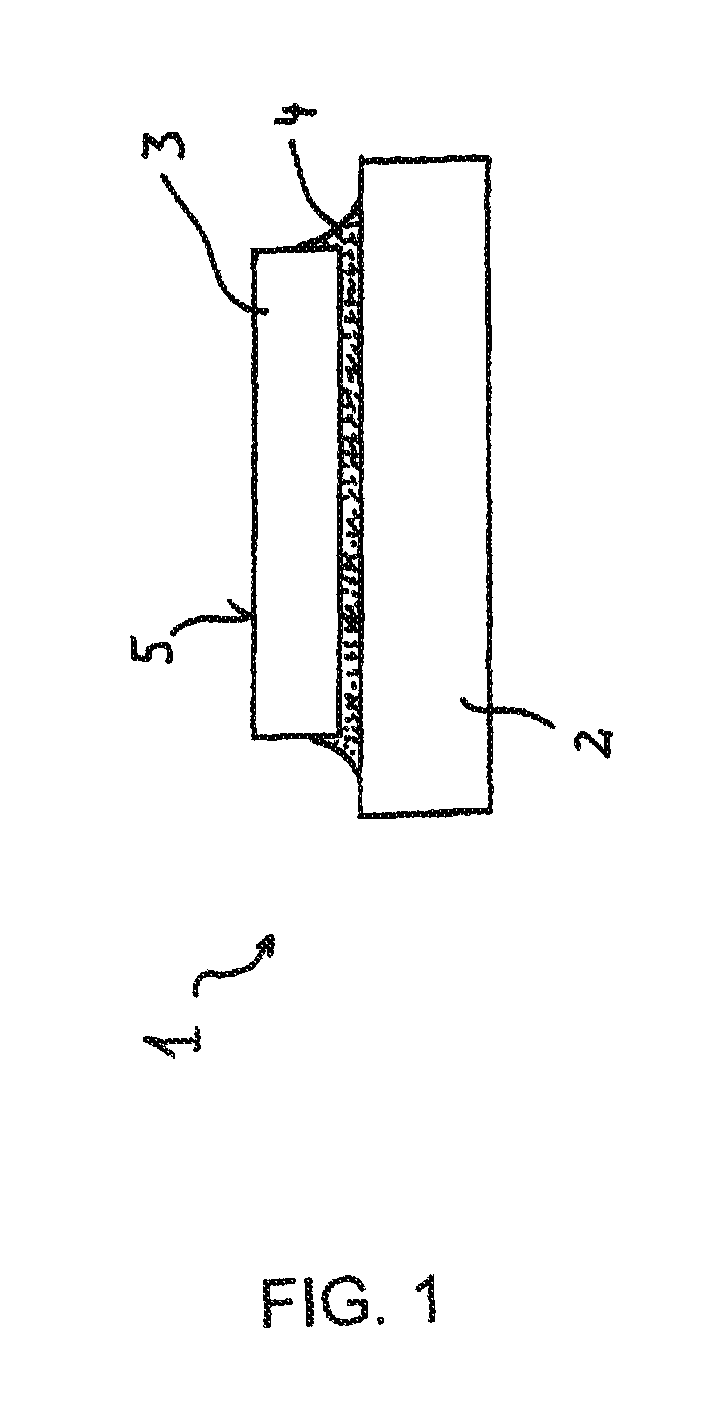
[0053]FIG. 1 shows a schematic representation of an embodiment of a stress measurement sensor 1 according to the invention. This sensor includes a base 2 and a sensor element 3, which is fixed on the base 2. The sensor element 3 operates according to the SAW principle. For this reason, a sensor surface 5 is thereby provided, disposed opposite the base 2, which surface has corresponding, well-known patterns, not shown here, wherein surface acoustic waves, the characteristics of which are evaluated for the measurement, extend along said sensor surface. The body of the sensor element 3 is formed from a piezoelectric carrier crystal. “Carrier crystal” is therefore not understood to be a pure crystalline material, but may also be a (partially) amorphous material, such as a ceramic.

[0054]The sensor element 3 is fixed to the base 2 by means of a joining material 4, and fastened thereto. Mechanical tensions or stresses exerted on the sensor element 3 are transmitted to the base 2 by means o...


PUM

PropertyMeasurementUnit
process temperatureaaaaaaaaaa
temperatureaaaaaaaaaa

Abstract

A stress measurement sensor provided with a sensor element that operates according to the SAW principle, comprising a base composed of a first material and the sensor element, which is fixed to the base with a joining material, is to be developed such that it can also be used at higher temperatures and has improved measurement properties. In addition, it is suggested that the joining material be a glass solder.

Description

BACKGROUND OF THE INVENTION[0001]1. Technical Field[0002]The invention relates to a stress measurement sensor, which has a sensor element that operates according to the SAW principle, which is connected to a base by means of a joining material.[0003]2. Background Information[0004]A sensor element that operates according to the SAW principle, which is a component of a generic stress measurement sensor, refers to surface acoustic waves, abbreviated as SAW, and the sensor element thereof, which utilizes running characteristics that are dependent on external influences. Such sensor elements typically comprise a piezoelectrically active carrier crystal, on which patterns have been applied to a sensor surface, such, as in particular, transducer patterns and acoustic reflectors. Surface acoustic waves are created on the sensor surface by means of the electrical excitation of the carrier crystal, which propagate across this sensor surface at a propagation velocity. Stress sensors having suc...

Claims


Application Information

Patent Timeline
Patent Type & Authority Patents(United States)
IPC IPC(8): G01B7/16G01L1/16G01B7/00H03H3/02G01L9/00
CPCG01L1/165G01B7/00H03H3/02G01L9/0042H03H2003/028Y10T29/42
Inventor HELBIG, CHRISTIANLOTZ, SEBASTIAN
Owner HORST SIEDLE GMBH & CO KG