
Scalable motion control system

a motion control system and scalable technology, applied in the direction of program control, total factory control, instruments, etc., can solve the problems of difficult to achieve satisfactory control in the event of a failure, high cost of remote controllers, and limited scalability of systems

Active Publication Date: 2011-03-08
BOOKS AUTOMATION US LLC
View PDF67 Cites 108 Cited by
  • Summary
  • Abstract
  • Description
  • Claims
  • Application Information

AI Technical Summary

Benefits of technology

[0004]The networked architecture opens numerous challenges in the areas of the division of the controls intelligence between the master and remote controllers, implementation of advanced control algorithms, communication network utilization, synchronization of components driven by different remote controllers, handling of events associated with inputs on multiple remote controllers, such as capturing positions of multiple axes of motion, accommodating a human presence in the work space, and dealing with power loss situations.
[0006]The benefits of a highly centralized architecture include the ability to provide advanced control algorithms, which often require real-time information from multiple axes, such as multi-input-multi-output (MIMO) control, and can be conveniently implemented on the master controller. The remote controllers in such an architecture require comparatively low computational power and small amounts of on-board memory, allowing for a relatively simple and inexpensive design.
[0008]In contrast, control systems with distributed control algorithms, which close the control loops on the remote controllers, executing on trajectory information received from the master controller, utilize comparatively low network traffic and substantially less time-critical data that may be conveniently buffered at the remote controllers to improve the overall capacity margin of the communication network. This approach may provide desirable scalability of the control system since increasing the number of remote controllers for additional axes automatically increases the overall computational power available for execution of the control loops. Furthermore, the remote controllers, being capable of generating simple trajectories and running control algorithms, have enough intelligence to support failure-related operations, such as a controlled stop, in the case of a failure of the communication network.

Problems solved by technology

The networked architecture opens numerous challenges in the areas of the division of the controls intelligence between the master and remote controllers, implementation of advanced control algorithms, communication network utilization, synchronization of components driven by different remote controllers, handling of events associated with inputs on multiple remote controllers, such as capturing positions of multiple axes of motion, accommodating a human presence in the work space, and dealing with power loss situations.
These systems usually have limited scalability because the maximum number of axes is constrained by the computational power of the master controller as well as the bandwidth of the communication network.
In addition, since the remote controllers may not have enough intelligence to autonomously support failure-related operations, such as performing a controlled stop of the respective motion axes in the case of a failure of the communication network, satisfactory control in the event of a failure may be problematic to achieve.
However, the additional intelligence of the remote controllers in the distributed architecture requires more computational power and memory, which generally makes the remote controllers more expensive.
Also, implementation of full MIMO control algorithms is problematic since the control algorithms running on one remote controller generally do not have real-time access to the states of the axes driven by other remote controllers.
These types of systems are generally expensive and have more capability than required for low-end machinery or systems requiring lower levels of integrity, such as Category 2 or 3.
A machine designer who wishes to implement an alternative solution to programmable integrity to avoid the added cost of the specialized high-end electronics is faced with an extremely complex task of making the electronics, network and software of a control system meet integrity requirements and obtaining regulatory authority or auditor approval.
Another issue with the existing technology that implements a specified level of integrity is size and form-factors, which are unsuitable for integrity applications with stringent space constraints.

Method used


Image

  • Scalable motion control system
  • Scalable motion control system
  • Scalable motion control system

Examples


Embodiment Construction

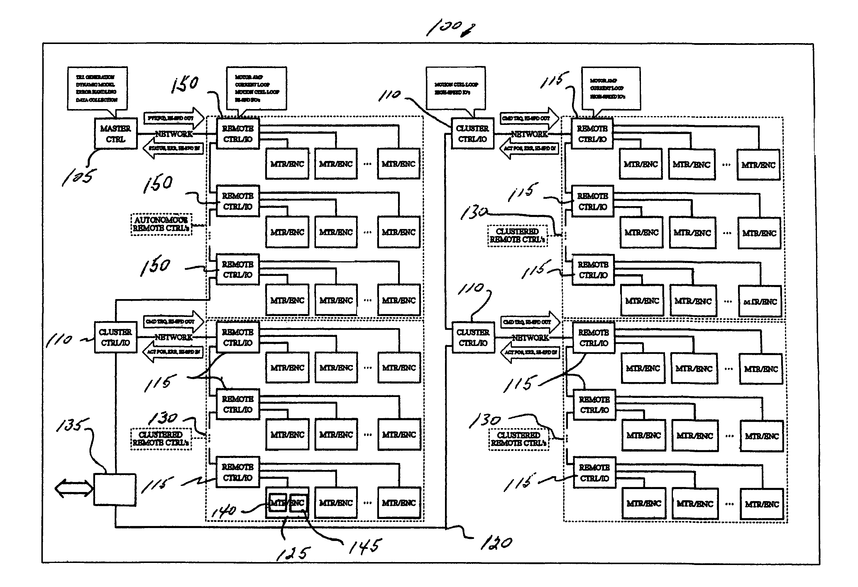
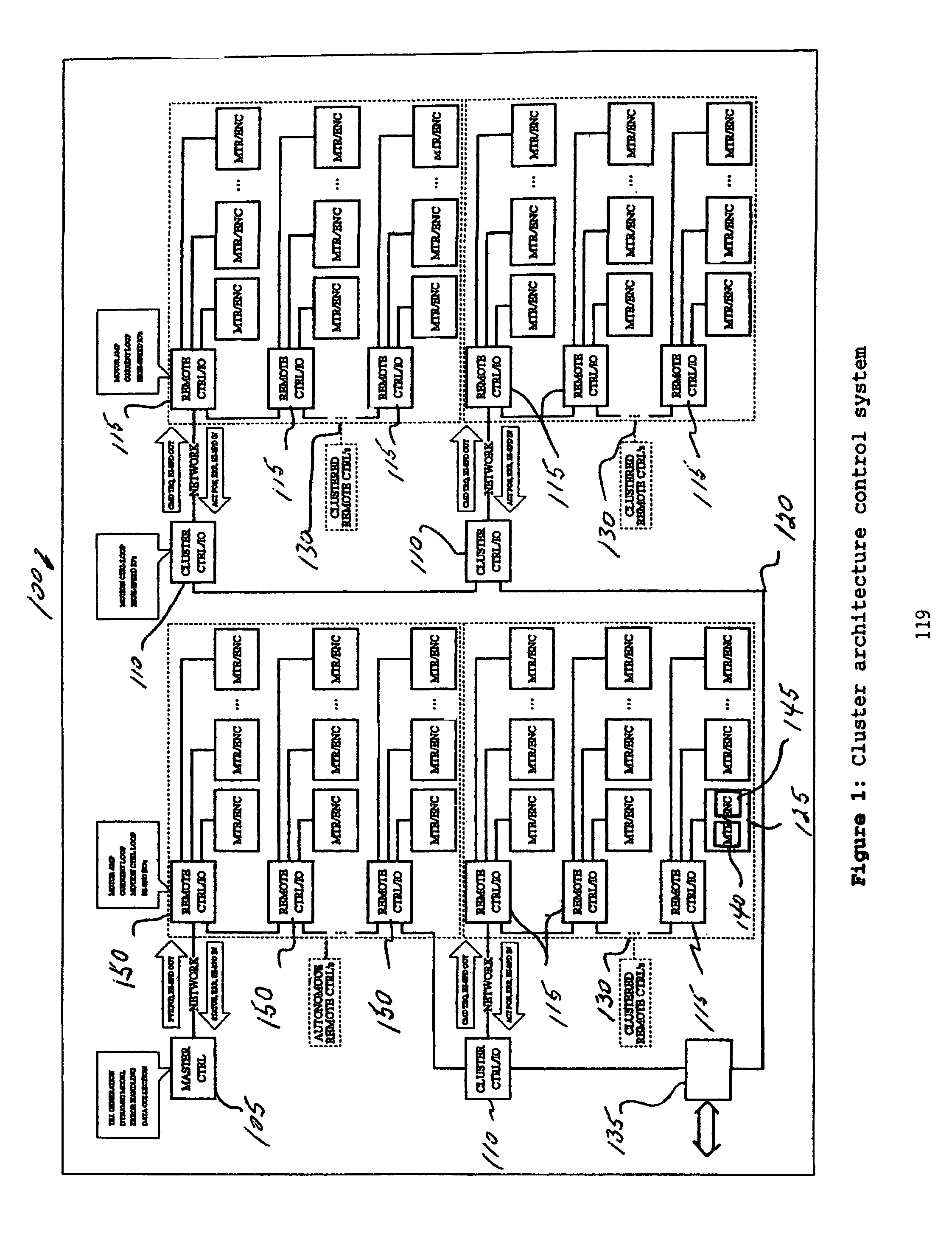
[0015]The disclosed embodiments are directed to a control system including a clustered architecture having a master controller, a central control section including one or more first remote controllers under direct control of the master controller and a distributed control section including a cluster controller controlled by the master controller, wherein the cluster controller controls the activities of one or more second remote controllers. Each of the first and second remote controllers are utilized to drive one or more axes.

[0016]The disclosed embodiments are also directed to a method of operating an axis of a control system that includes generating a trajectory for the axis in terms of a position, velocity, and acceleration for each point of a plurality of points on the trajectory, and calculating an inverse dynamic model of the axis to determine a gain value and a feedforward term for each point.

[0017]The disclosed embodiments are further directed to a method of synchronizing n...


PUM


Abstract

A control system includes a clustered architecture having a master controller, a central control section including one or more first remote controllers under direct control of the master controller, and a distributed control section including a cluster controller controlled by the master controller. The cluster controller controls the activities of one or more second remote controllers. Each of the first and second remote controllers are utilized to drive one or more axes.

Description

CROSS-REFERENCE TO RELATED APPLICATION(S)[0001]This application claims the benefit of U.S. Provisional Application No. 60 / 688,636, filed Jun. 8, 2005 which is incorporated by reference herein in its entirety.BACKGROUND[0002]The disclosed embodiments are related to a control system for complex multi-axis non-linear machines, in particular, to a system for accurate and synchronized control of precision robots with a desirable combination of performance, flexibility, and scalability.BRIEF DESCRIPTION OF RELATED DEVELOPMENTS[0003]As a result of technological improvements in the area of electronics and communication, control technology for complex motion systems has taken a clear direction toward a networked architecture. A networked solution utilizes multiple simple controllers, referred to as remote controllers, which are located close to the components subject to control, such as motors and other actuators, and are coordinated by a master controller through a communication network.[00...

Claims


Application Information

Patent Timeline
Patent Type & Authority Patents(United States)
IPC IPC(8): G05B15/00G06K9/00G06F19/00G05B19/418G05B19/18B05C11/00
CPCG05B19/4148G05B19/4185G05B2219/33277G05B2219/31207Y02P90/02G05B19/18
Inventor HOSEK, MARTINBEALE, STUARTBOTEV, ROUMENCOADY, MATTHEWHOFMEISTER, CHRISTOPHERIVES, MARKMOURA, JAIROCAVENEY, ROBERT
Owner BOOKS AUTOMATION US LLC
Learn More