Network interface with clock recovery module on line card

a clock recovery and network interface technology, applied in the field of clock synchronization, can solve the problems of complex and flexible plls for new applications with specific synchronization requirements

Active Publication Date: 2015-12-08
MICROSEMI SEMICON
View PDF2 Cites 50 Cited by
  • Summary
  • Abstract
  • Description
  • Claims
  • Application Information

AI Technical Summary

Problems solved by technology

New applications with specific synchronization requirements demand complex and flexible PLLs.

Method used


Image

  • Network interface with clock recovery module on line card
  • Network interface with clock recovery module on line card
  • Network interface with clock recovery module on line card

Examples


Embodiment Construction

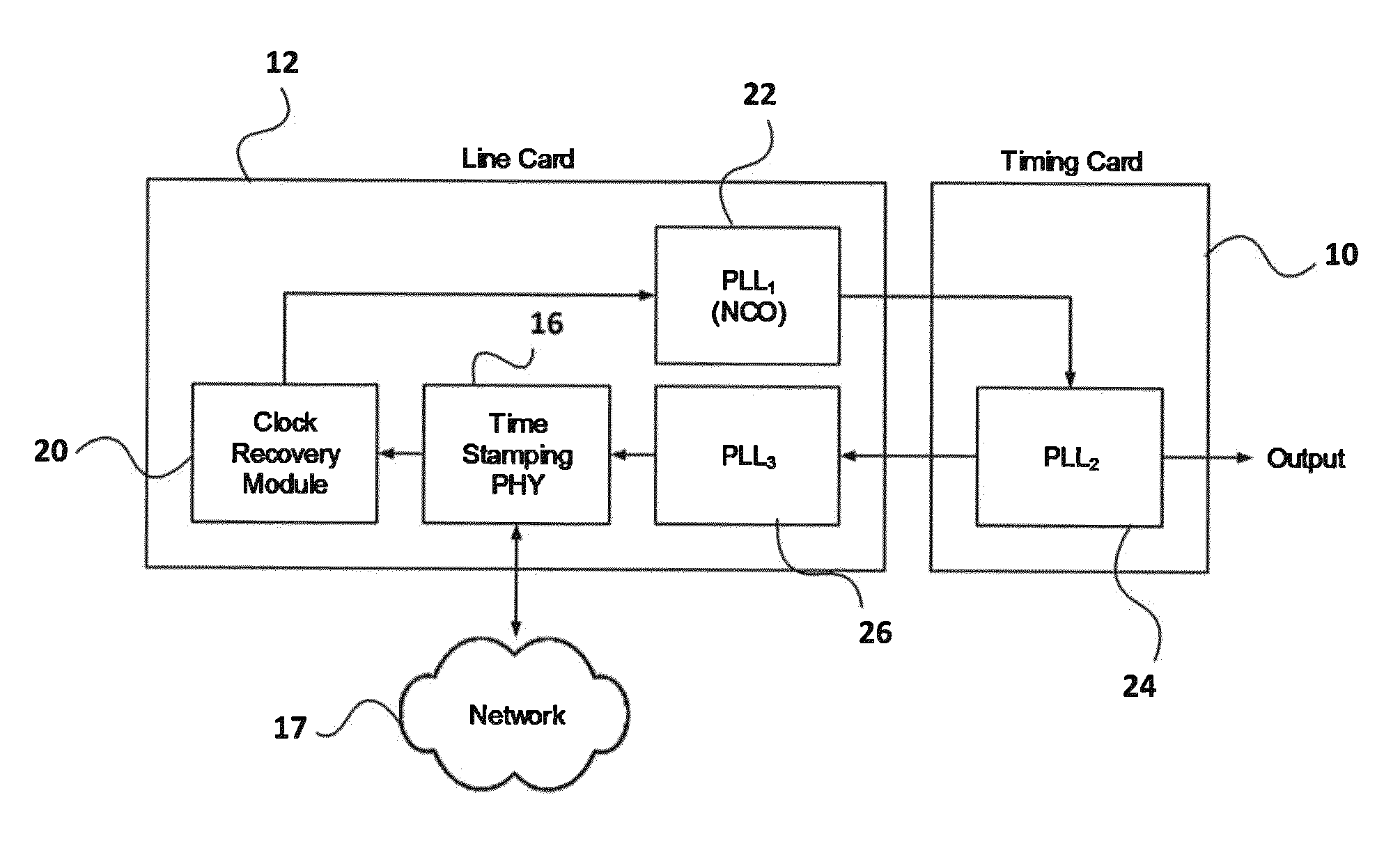
[0021]Embodiments of the invention implement a clock recovery algorithm on the line cards and use the output of the timing card filter to drive the time stamping physical interfaces (PHYs) on the line cards.

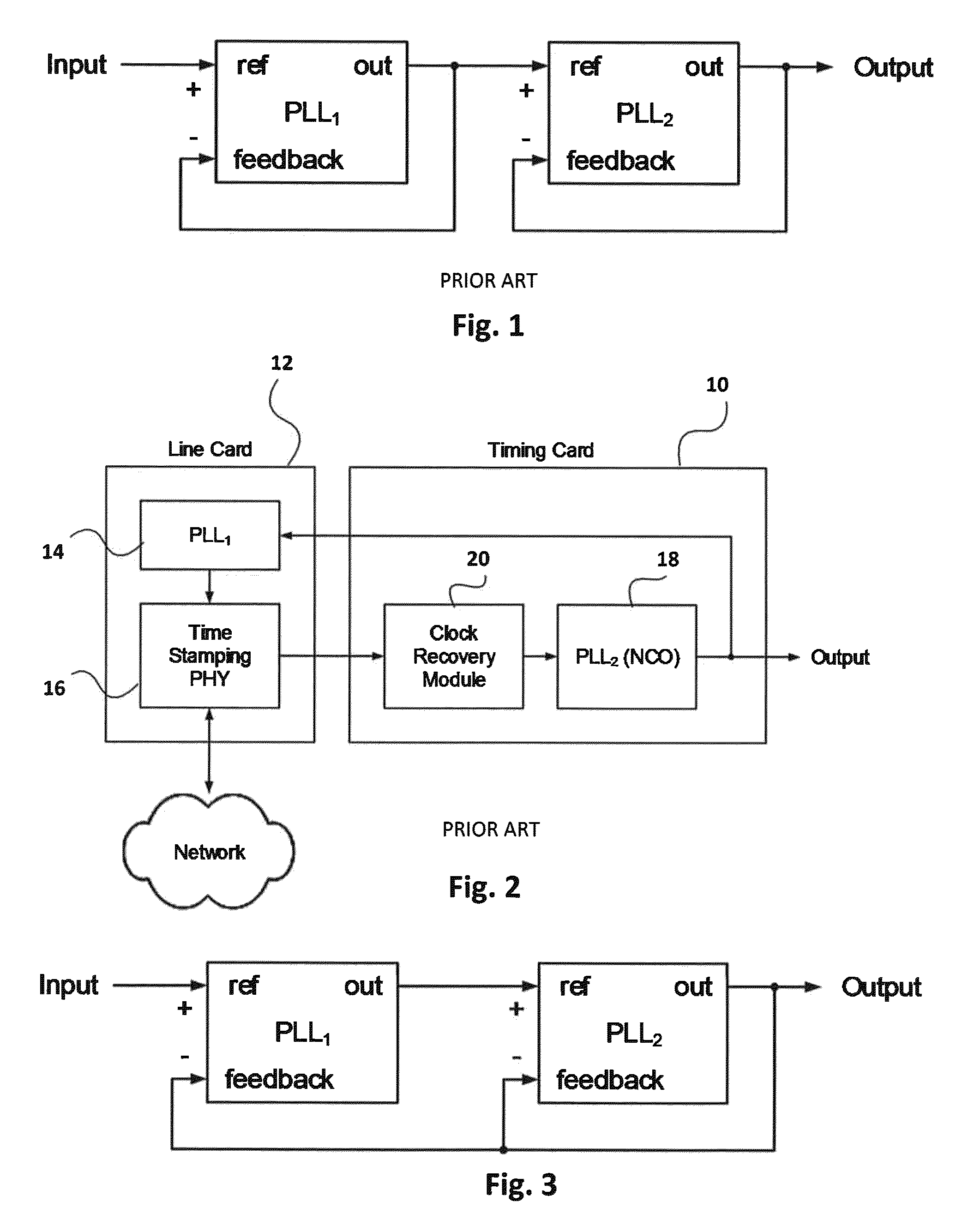
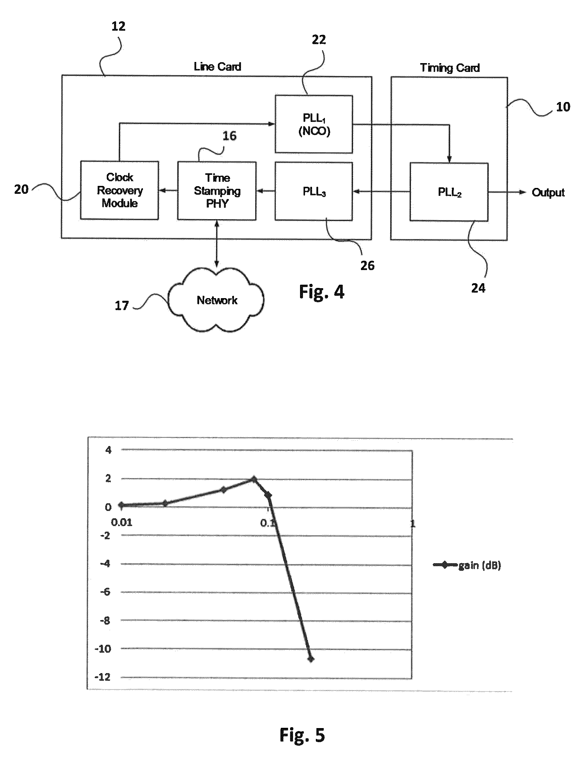
[0022]This arrangement simplifies the timing card design because no ToP data needs to be transferred up the timing chain from the line card to the timing card. The timing card only needs electrical clock signals as inputs and outputs. However, a side effect of this configuration is that the phase locked loop for the timing card PLL is actually inside the feedback loop of the ToP clock recovery module as shown in FIG. 4. This arrangement in effect creates multi-loop PLL system of the type shown in FIG. 3. Compared to a cascaded PLL system, this multi-loop PLL may change the system's transfer function such that undesirable gain peaking is introduced. Gain peaking, which is a term used in PLL system theory, refers to fact that the PLL gain transfer function, at certain frequency may...


PUM


Abstract

A network interface for recovering timing information over packet networks has line card at the edge of a local network and a timing card separate from the line card. A physical interface time-stamps incoming timing packets based on smoothed recovered clock signals. A clock recovery module on the line card generates timing signals from the time-stamped incoming timing packets. A first phase locked generates raw clock signals from the timing signals. A second phase locked loop on the timing card generates the smoothed clock signals from said raw clock signals and applies them to the clock recovery module on the line card.

Description

CROSS REFERENCE TO RELATED APPLICATION[0001]This application claims the benefit under 35 USC 119 (e) of U.S. provisional application No. 61 / 927,013 filed Jan. 14, 2014, the contents of which are herein incorporated by reference.FIELD OF THE INVENTION[0002]This invention relates to the field of clock synchronization, and in particular to a network interface with a clock recovery module on the line card. The invention further relates to a method of compensating for gain peaking when a phase locked loop (PLL) is located inside the feedback loop of another PLL.BACKGROUND OF THE INVENTION[0003]The use of PLLs in communications over the years has become an ever-growing trend. New applications with specific synchronization requirements demand complex and flexible PLLs. Economic and integration reasons are pushing for support for multiple application scenarios, each requiring different standards employing different synchronization clock criteria. User configurable flexibility has become ess...

Claims


Application Information

Patent Timeline
Patent Type & Authority Patents(United States)
IPC IPC(8): H03D3/34H04L7/033
CPCH04L7/0331H04J3/0697H03L7/00H03L7/093
Inventor RAHBAR, KAMRANCROSBY, PETER
Owner MICROSEMI SEMICON
Why Eureka
Try Eureka