
Display device and method for driving the same

Active Publication Date: 2015-07-02
LG DISPLAY CO LTD
View PDF5 Cites 49 Cited by
  • Summary
  • Abstract
  • Description
  • Claims
  • Application Information

AI Technical Summary

Benefits of technology

The invention provides a display device and a way to use it that stops problems with the part that controls the display. This helps prevent malfunctions caused by too much power in the display part.

Problems solved by technology

Hence, it is difficult to reduce a width of the source PCB.
Because an amount of data to be transmitted increases when the timing controller is connected to with the source driver ICs in the point-to-point manner, a data transmission frequency in the EPI manner is greater than that in the point-to-point manner However, the EPI manner easily distorts a waveform of a pair of signals (P, N) transmitted to the source driver ICs due to an external noise, impedance mismatching of a printed circuit board (PCB), a difference between lengths of the signal line pair of the timing controller and the source driver ICs, etc.
Hence, an abnormal noise is displayed on the screen.
As a result, it is difficult to apply the EPI technology in a state where the timing controller is connected with the source driver ICs in the multidrop manner.

Method used


Image

  • Display device and method for driving the same
  • Display device and method for driving the same
  • Display device and method for driving the same

Examples


Embodiment Construction

[0033]Reference will now be made in detail to embodiments of the invention, examples of which are illustrated in the accompanying drawings. Wherever possible, the same reference numbers will be used throughout the drawings to refer to the same or like parts. It will be paid attention that detailed description of known arts will be omitted if it is determined that the arts can mislead the embodiments of the invention.

[0034]A display device according to an exemplary embodiment of the invention may be implemented as a flat panel display, such as a liquid crystal display (LCD), a field emission display (FED), a plasma display panel (PDP), and an organic light emitting display. In the following description, the embodiment of the invention will be described using the liquid crystal display as an example of the flat panel display. Other flat panel displays may be used.

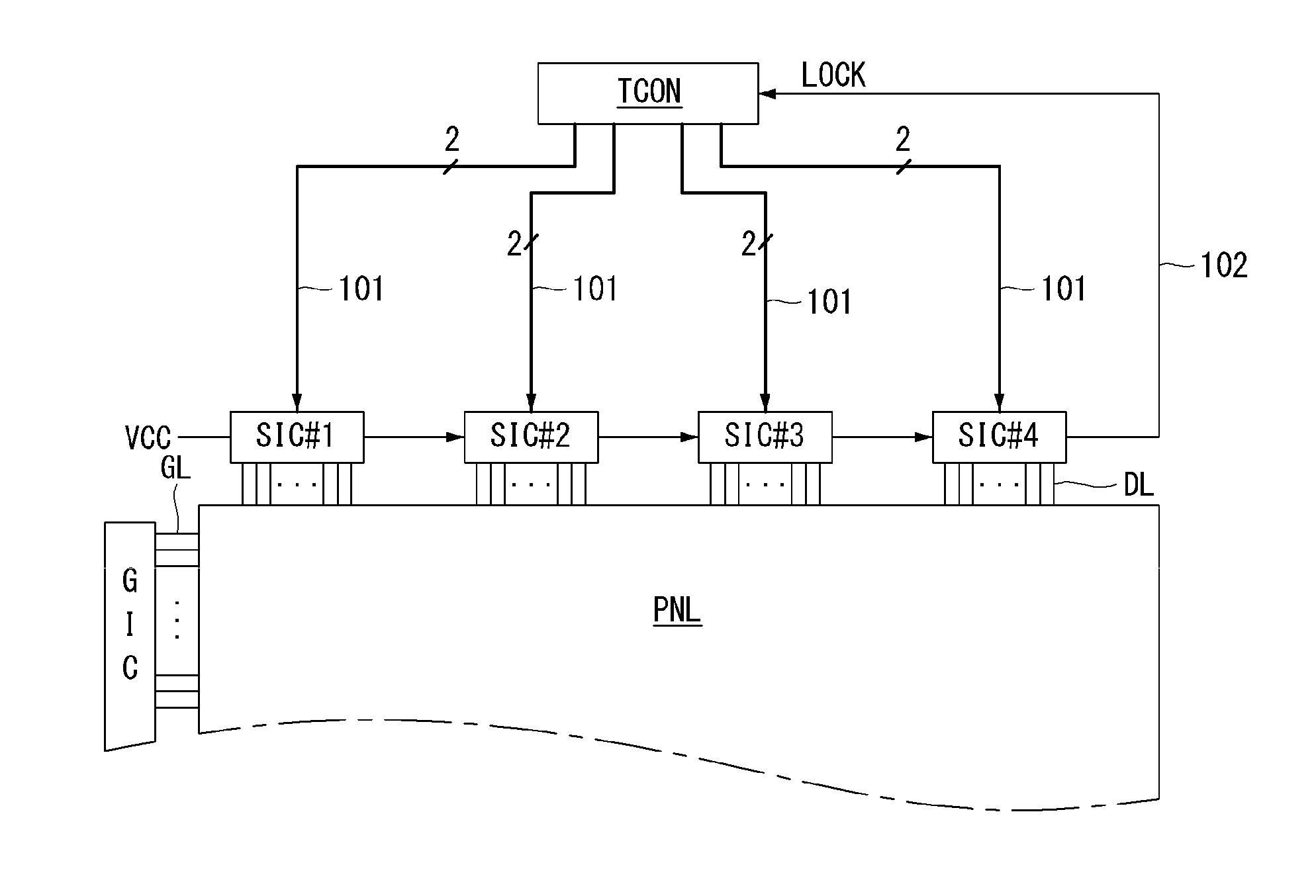
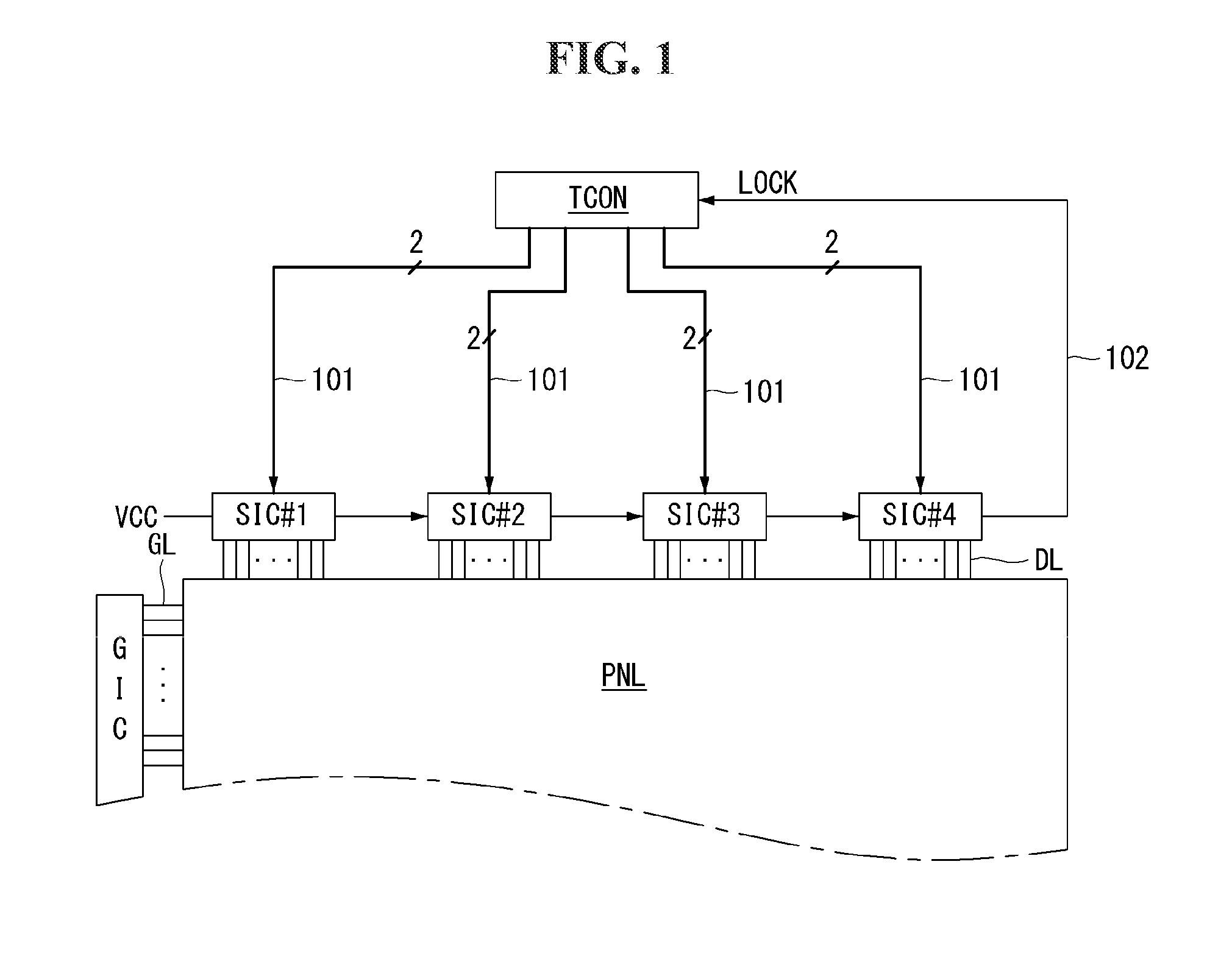
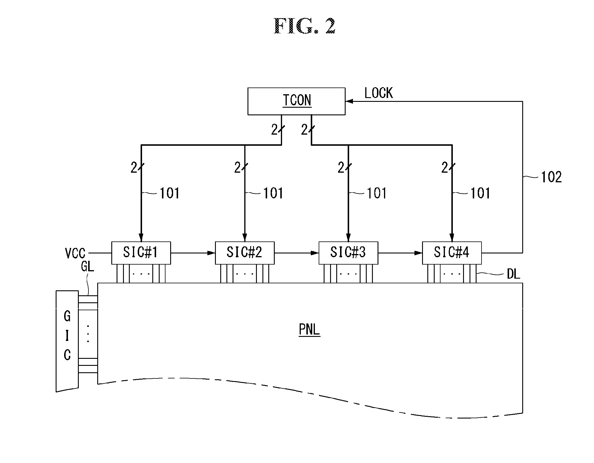
[0035]As shown in FIG. 1, a liquid crystal display according to the embodiment of the invention includes a liquid crystal d...


PUM


Abstract

A display device includes a source driver integrated circuit (IC) including an equalizer for boosting a data signal received through a pair of signal lines depending on an equalization (EQ) setting value and a clock recovery circuit recovering a clock of the data signal, and a timing controller, which is connected to the source driver IC through the signal line pair and transmits the data signal to the source driver IC. The source driver IC samples the data signal in conformity with a timing of an internal clock output when the clock recovery circuit is in a lock state. The source driver IC further includes an equalizer control circuit for initializing the equalizer when the clock recovery circuit is in an unlock state and the EQ setting value is changed.

Description

[0001]This application claims the benefit of Korean Patent Application No. 10-2013-0166670 filed on Dec. 30, 2013, the entire contents of which is incorporated herein by reference for all purposes as if fully set forth herein.BACKGROUND OF THE INVENTION[0002]1. Field of the Invention[0003]Embodiments of the invention relate to a display device and a method for driving the same.[0004]2. Discussion of the Related Art[0005]An active matrix liquid crystal display displays a motion picture using a thin film transistor (TFT) as a switching element. The active matrix liquid crystal display may be made to be smaller and more compact than a cathode ray tube (CRT) and thus may be applied to display units of portable information appliances, office equipments, computers, etc. Further, the active matrix liquid crystal display may be applied to televisions and thus is rapidly replacing the cathode ray tube.[0006]A liquid crystal display includes a plurality of source driver integrated circuits (I...

Claims


Application Information

Patent Timeline
IPC IPC(8): G09G3/36
CPCG09G3/3685G09G2370/14G09G2310/0289G09G2310/027G09G3/2096G09G3/3614G09G5/008G09G2370/08G09G3/20G09G3/36
Inventor PARK, DAEKYU
Owner LG DISPLAY CO LTD
Learn More