Indexable cutting insert and a tool for chip removing machining, as well as a basic body for the tool

a technology of indexable cutting inserts and tools, which is applied in the direction of cutting inserts, manufacturing tools, shaping cutters, etc., can solve the problem that the cutting insert cannot be installed in the nose of the tool, and achieve the effect of facilitating the understanding of the nature of the cutting inser

Active Publication Date: 2015-12-15
SANDVIK INTELLECTUAL PROPERTY AB
View PDF20 Cites 0 Cited by
  • Summary
  • Abstract
  • Description
  • Claims
  • Application Information

AI Technical Summary

Benefits of technology

[0009]The present invention aims at obviating the above-mentioned, geometrically conditioned limitations of previously known, indexable cutting inserts having multiple cutting tips and cutting edges, and at providing an improved cutting insert. Therefore, a primary object of the invention is to provide an indexable cutting insert having considerably more cutting tips and usable cutting edges than what previously has been considered to be possible, at the same time as the cutting insert should be so compact or space-efficient that the same can be installed in a tool basic body that is suitable for shoulder turning and shoulder milling, respectively, or other machining operations that require that a part of the tool basic body is contained within an angle of 90°. A further object is to provide a cutting insert, by means of which the generation of heat in the cutting zone can be reduced and thereby counteract heat-conditioned damage to the active cutting edge. It is also an object to provide a cutting insert, the inactive cutting edges of which are well protected during the chip removal of the active cutting edge. In such a way, it is guaranteed that the unused cutting edges retain their micro geometry until the same are indexed up into an active position. Still another object is to provide a cutting insert having so many usable cutting edges that the manufacturing cost for the individual cutting edge in relation to the total volume of the cutting insert becomes minimal. In other words, the machining cost for the user, in relation to the amount of cemented carbide included in the cutting insert, should be minimized.
[0011]In one embodiment, first and second, diametrically opposed cutting tips, along a common, first co-ordinate axis, are oriented with their reference planes perpendicular to each other, the two other co-ordinate axes intersecting an imaginary extension of the reference plane of the individual, first or second cutting tip at an angle of 45°. In such a way, the cutting tips can be formed with a width that guarantees on one hand that the same become strong, and on the other hand that the active cutting tip obtains a large bearing surface and thereby a stable support on a main support surface included in the seat of the tool body. In addition, the inactive cutting tip, which is diametrically opposite the active cutting tip, can be housed in a comparatively narrow cavity in the tool body.
[0012]In a further embodiment, the individual cutting tip comprises on one hand an outer part, in which the cutting edge is included, and on the other hand an inner part that is positioned closest to the core and has a quadrangular cross-sectional shape. By in this way forming the individual cutting tip with an outer part as well as an inner part located between the same and the core, the active cutting edge can be located at a certain distance from the core, whereby the core and the inactive cutting tips can be housed a good distance into the seat of the basic body. Furthermore, by the quadrangular cross-sectional shape of the inner part of the cutting tip, surfaces, which meet each other at a right angle, can in an advantageous way be utilized for engaging and be supported in V-shaped chutes in the seat of the basic body.
[0015]In yet an embodiment, the inner part of the cutting tip has a rectangular cross-sectional shape. In such a way, the individual cutting tip obtains an optimum width and an optimum bearing surface for abutment against a main support surface in the seat of the tool body. In addition, the active main edges can be given a large edge length adjacent to possible chip-formers, which is something that in turn allows large cutting depths.
[0017]In another embodiment, the individual cutting tip is located with its reference plane running between two diagonally opposite corners along the individual limiting surface of the cubical core. Also this embodiment contributes to optimizing the width and strength of the cutting tip.TERMINOLOGY

Problems solved by technology

This means that such a cutting insert cannot per se be installed in a nose in a tool for turning of a shoulder.

Method used


Image

  • Indexable cutting insert and a tool for chip removing machining, as well as a basic body for the tool
  • Indexable cutting insert and a tool for chip removing machining, as well as a basic body for the tool
  • Indexable cutting insert and a tool for chip removing machining, as well as a basic body for the tool

Examples


Embodiment Construction

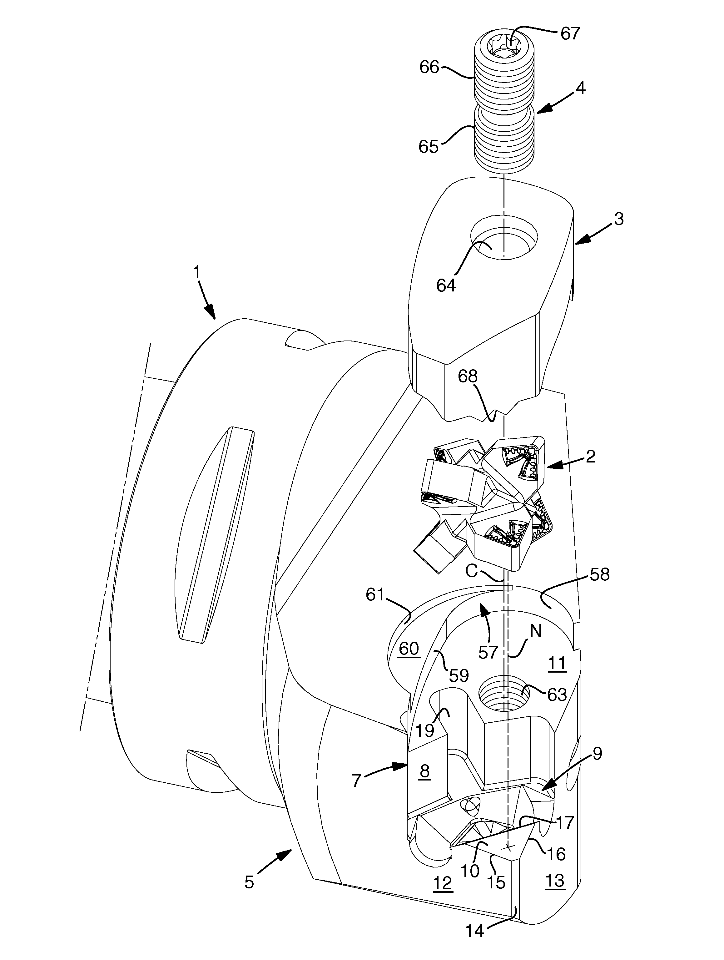
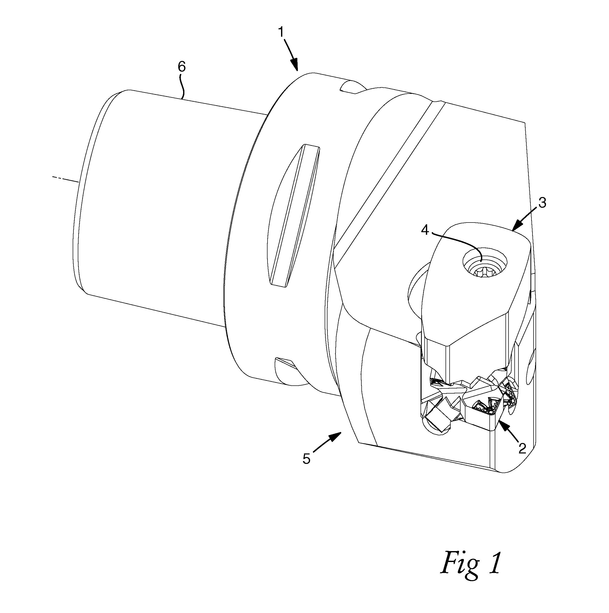
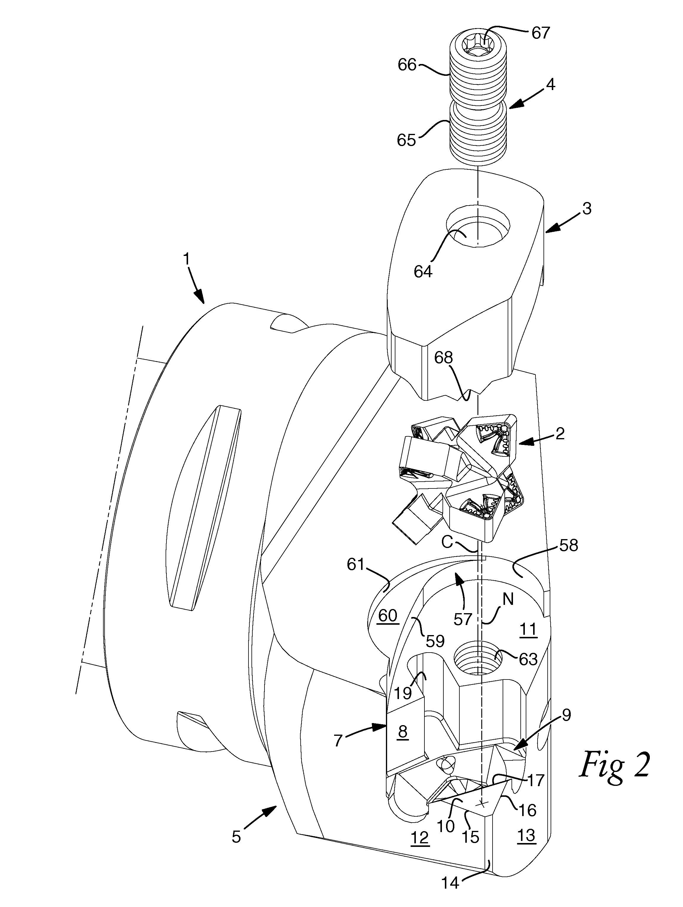
[0043]In FIGS. 1-4, a tool made in accordance with the invention for chip removing or cutting machining is shown, more precisely in the form of a turning tool. The main components of the tool are a basic body 1 and a replaceable cutting insert 2. In addition, a tightening device 3 is included in the form of a clamp, which has the purpose of clamping the cutting insert in a seat in the basic body 1. This is achieved by means of a screw 4 having double threads. In a traditional way, the cutting insert 2 may be manufactured from cemented carbide, while the basic body 1 is manufactured from a steel billet, more precisely by cutting machining.

[0044]In the example, the basic body 1 is formed with a head 5 and a fixing part 6, by means of which the basic body can be fixed in an appurtenant machine. The seat in the basic body, which has the purpose of receiving the cutting insert 2, is generally designated 7 and is delimited by a wall 8 as well as a bottom that in its entirety is designated...


PUM

PropertyMeasurementUnit
angleaaaaaaaaaa
corner angleaaaaaaaaaa
angleaaaaaaaaaa

Abstract

An indexable cutting insert for chip removing machining includes a plurality of cutting tips that protrude from a central core. Each of the individual tips include a cutting edge, which is formed in a transition between an upper side serving as chip surface and a clearance surface, which extends between the upper side and an under side. The cutting insert has six equally long cutting tips that are located in pairs along the co-ordinate axes of a three-dimensional, orthogonal system of co-ordinates, the origin of which is situated in the core. By arranging the cutting tips in this way, the inactive cutting tips, which are situated behind an active cutting tip, can be contained within a limited volume and therefore be installed in tool basic bodies having tapering parts. A tool equipped with the cutting insert according to the invention, as well as, a tool basic body is disclosed.

Description

RELATED APPLICATION DATA[0001]This application claims priority under 35 U.S.C. §119 to Swedish Patent Application No. 1250411-4, filed on Apr. 24, 2012, which the entirety thereof is incorporated herein by reference.TECHNICAL FIELD OF THE INVENTION[0002]In a first, vital aspect, this invention relates to an indexable cutting insert intended for chip removing machining and of the type that comprises a plurality of cutting tips that protrude from a central core and individually include a cutting edge, which is formed in a transition between an upper side serving as chip surface, and a clearance surface, which extends between the upper side and an under side.[0003]In a second aspect, the invention also relates to an assembled tool, which comprises on one hand a basic body having a seat situated in an area between two limiting surfaces of the basic body converging toward each other and delimited by a wall and a bottom, and, on the other hand, a cutting insert formed in accordance with t...

Claims


Application Information

Patent Timeline
Patent Type & Authority Patents(United States)
IPC IPC(8): B23B27/16B23C5/22B23C5/20B23B27/14
CPCB23C5/20B23B27/14B23B27/16B23C5/22B23B2200/048B23B2200/0423B23B2200/087Y10T407/22Y10T407/2272Y10T407/23B23B27/1611B23B27/00B23C2200/04
Inventor MOHSENI, MOJGAN
Owner SANDVIK INTELLECTUAL PROPERTY AB
Why Eureka
Try Eureka