
Hose attachment device for clearing drain lines

a technology for drain lines and hoses, applied in flush cleaning, lighting and heating apparatus, heating types, etc., can solve the problems of cumbersome use and easy loss

Active Publication Date: 2015-12-22
RS ACQUISITION SUB LLC
View PDF11 Cites 1 Cited by
  • Summary
  • Abstract
  • Description
  • Claims
  • Application Information

AI Technical Summary

Benefits of technology

The present invention is a device for attaching a hose to a source of pressurized gas or liquid for clearing HVACR drain lines. The device includes a cap with an open bottom and an interior cavity surrounded by the cap. The cap can receive a drain line extension. The hose extends through the top of the cap and into the interior cavity. The device has a threaded male fitting at the proximal end of the hose for engaging a female valve stem and a valve fitting at the distal end of the hose for engaging a male valve stem. The device allows for the controlled release of gas or liquid from the source to the drain line.

Problems solved by technology

It is not uncommon for these and other types of drain lines to occasionally become partially or completely clogged, resulting in a backup of condensate liquid in the drain line and the collection pan of the HVACR unit.
Hose attachment assemblies having a valve fitting and removable seal plug allow for inline injection of pressurized gas or liquid to flush clogs in an HVACR drain line; however, these attachment devices that are commonly used in the field include multiple parts that can be cumbersome to use and easy to lose.

Method used


Image

  • Hose attachment device for clearing drain lines
  • Hose attachment device for clearing drain lines
  • Hose attachment device for clearing drain lines

Examples


Embodiment Construction

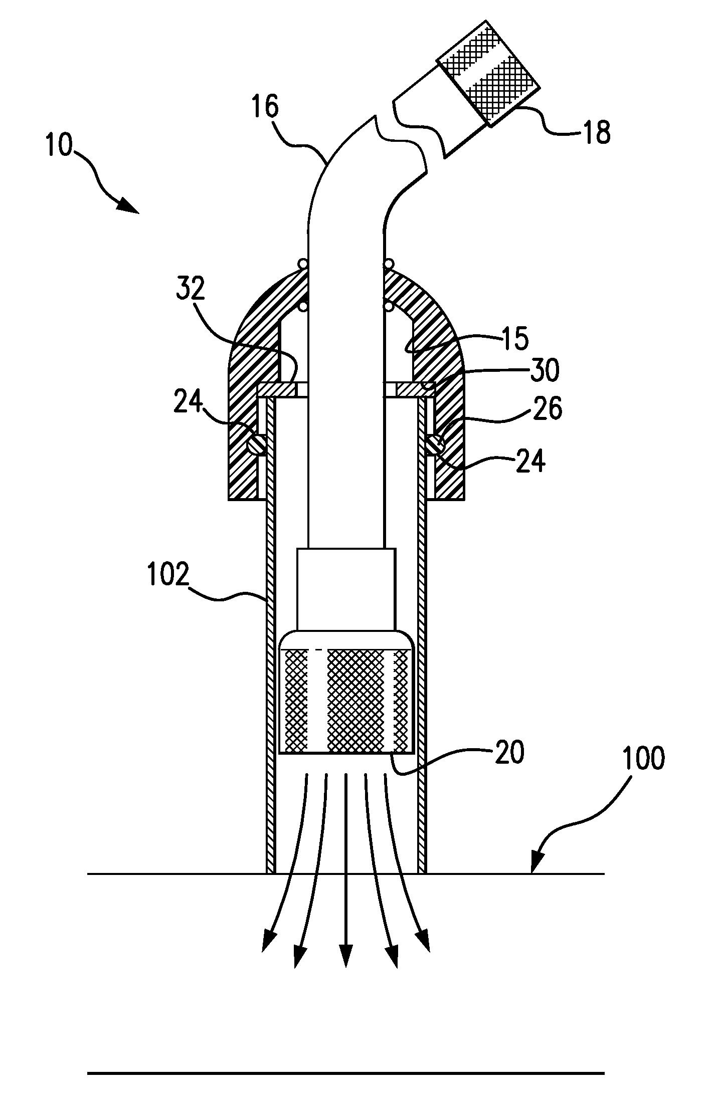
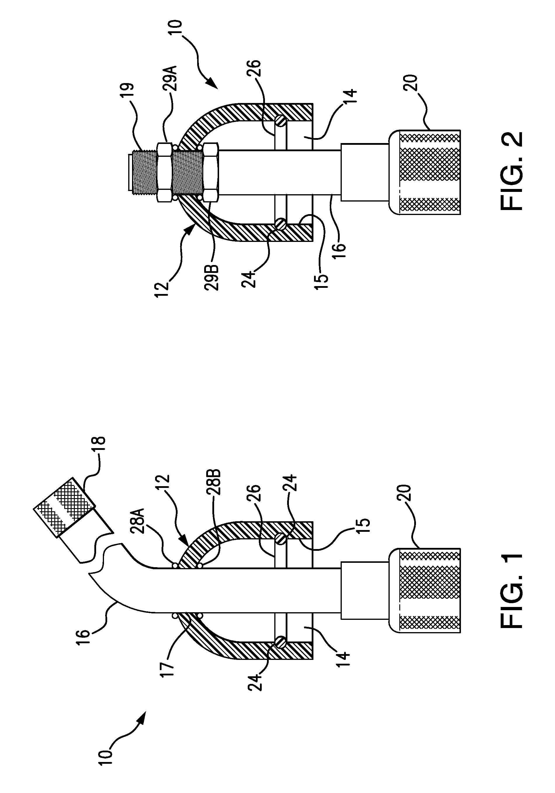
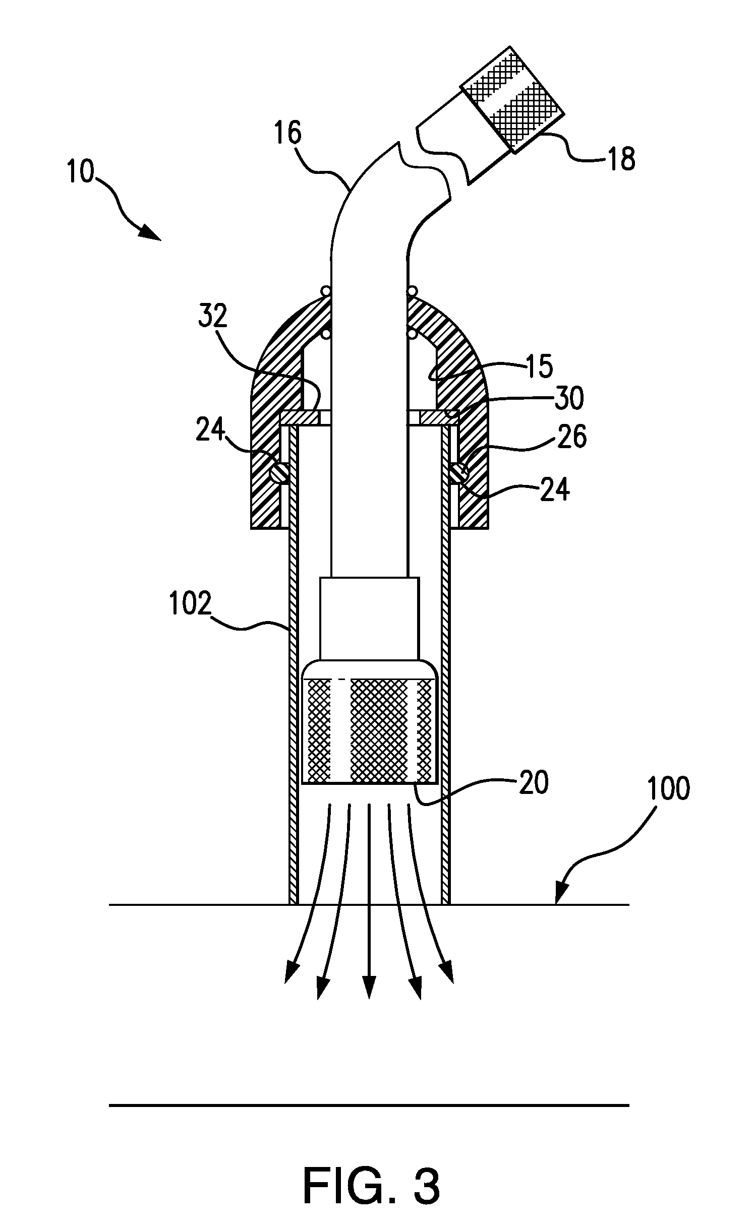
[0017]Referring to the several views of the drawings, the hose attachment device of the present invention for clearing HVACR drain lines 100 is shown and is generally indicated as 10.

[0018]Referring to FIGS. 1 and 2, the hose attachment device 10 includes a dome-shaped cap 12 having an open bottom end and an interior cavity 14 surrounded by an inner facing wall 15 of the cap 12 and communicating with the open bottom. It is noted that the term “dome-shaped” is not limited to the configuration shown in the drawings and includes any shape and configuration that meets the description herein and serves the same function, such as a flat top cap, all of which are fully contemplated within the spirit and scope of the invention. The open bottom end and the interior cavity 14 of the dome-shaped cap 14 are sized for engaged receipt of a drain line extension 102, such as a ¾″ drain line extension made from any known material such as, but not limited to PVC, CPVC or copper. A hose member 16 or o...


PUM


Abstract

A hose attachment device for use in combination with a source of pressurized gas or liquid for clearing HVACR drain lines. The device includes a cap having an interior cavity extending from an open bottom end that is sized for engaged receipt of an open-ended drain line extension. One embodiment of the device includes a hose extending through the top of the cap and having a fitting at the proximal end of the hose (extending from the top of the cap) that is sized for attachment to the pressurized source. A valve fitting at the distal end of the hose is sized for engaged receipt of a male valve stem, such as a Schrader valve. Another embodiment of the invention includes a valve fitting extending through top of the cap. A further embodiment of the invention includes an upper component and a lower component forming the cap, wherein the upper component is securable to a nozzle of a garden hose and the bottom component is securable to an open-ended drain line extension.

Description

BACKGROUND OF THE INVENTION[0001]1. Field of the Invention[0002]This invention relates to cleaning drain lines and other fluid transfer conduits and, more particularly, to a hose attachment device for introducing a pressurized flow of gas or liquid into a drain line or other conduit in order to clear a clog.[0003]2. Discussion of the Related Art[0004]In various systems and equipment, there is a need to transfer and / or drain liquid from the equipment to a separate location. For example, in air conditioning and refrigeration systems, liquid condensate is directed through a drain line that leads to an appropriate discharge location, such as the exterior of a building. It is not uncommon for these and other types of drain lines to occasionally become partially or completely clogged, resulting in a backup of condensate liquid in the drain line and the collection pan of the HVACR unit. In order to flush clogs and prevent accidental condensate overflows in HVACR condensate drain lines, a p...

Claims


Application Information

Patent Timeline
Patent Type & Authority Patents(United States)
IPC IPC(8): F24F13/22B08B9/027F24F13/02F28G9/00B08B9/032F16L21/03
CPCF24F13/222B08B9/027F24F13/02B08B9/0321B08B9/0328Y10T137/4259F24F2013/227F24F2221/22F24F2221/225F28F2265/22F28G9/00F16L21/03
Inventor OAKNER, STUARTOAKNER, DONNA
Owner RS ACQUISITION SUB LLC
Learn More