
Method and apparatus for monitoring electro-magnetic radiation power in solid freeform fabrication systems

a technology of electromagnetic radiation and fabrication system, applied in the direction of additive manufacturing process, manufacturing tools, nuclear engineering, etc., can solve the problems of less effective wavelengths of light, less than 10% light intensity of light source,

Active Publication Date: 2016-01-26
STRATASYS LTD
View PDF2 Cites 245 Cited by
  • Summary
  • Abstract
  • Description
  • Claims
  • Application Information

AI Technical Summary

Problems solved by technology

The intensity of the light source, however, may decrease in more that 10% from various reasons including deterioration of the light source, deterioration of a reflector of the light source, appearance of mist or undesired splashes of material on the protective glass of and the like.
Further, the desired spectral region of the light source may shift so that light may be at less effective wavelengths.

Method used


Image

  • Method and apparatus for monitoring electro-magnetic radiation power in solid freeform fabrication systems
  • Method and apparatus for monitoring electro-magnetic radiation power in solid freeform fabrication systems
  • Method and apparatus for monitoring electro-magnetic radiation power in solid freeform fabrication systems

Examples


Embodiment Construction

[0010]In the following detailed description, numerous specific details are set forth in order to provide a thorough understanding of the invention. However, it will be understood by those of ordinary skill in the art that the present invention may be practiced without these specific details. In other instances, well-known methods, procedures, components and circuits may not have been described in detail so as not to obscure the present invention.

[0011]Although embodiments of the invention are not limited in this regard, discussions utilizing terms such as, for example, “processing,”“computing,”“calculating,”“determining,”“establishing”, “analyzing”, “checking”, or the like, may refer to operation(s) and / or process(es) of a computer, a computing platform, a computing system, or other electronic computing device which may be included in a printing machine, that may manipulate and / or transform data represented as physical (e.g., electronic) quantities within the computer's registers an...


PUM

PropertyMeasurementUnit
wavelength rangeaaaaaaaaaa

Abstract

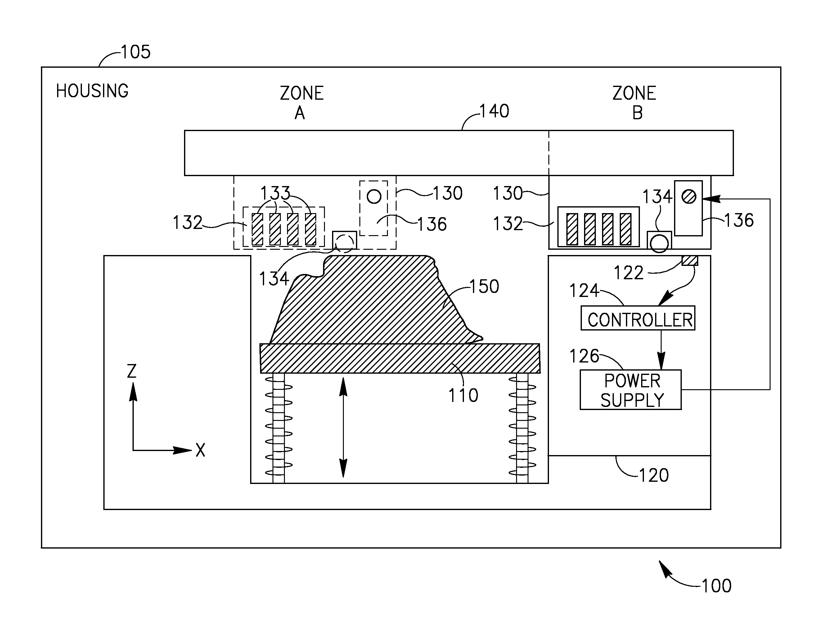
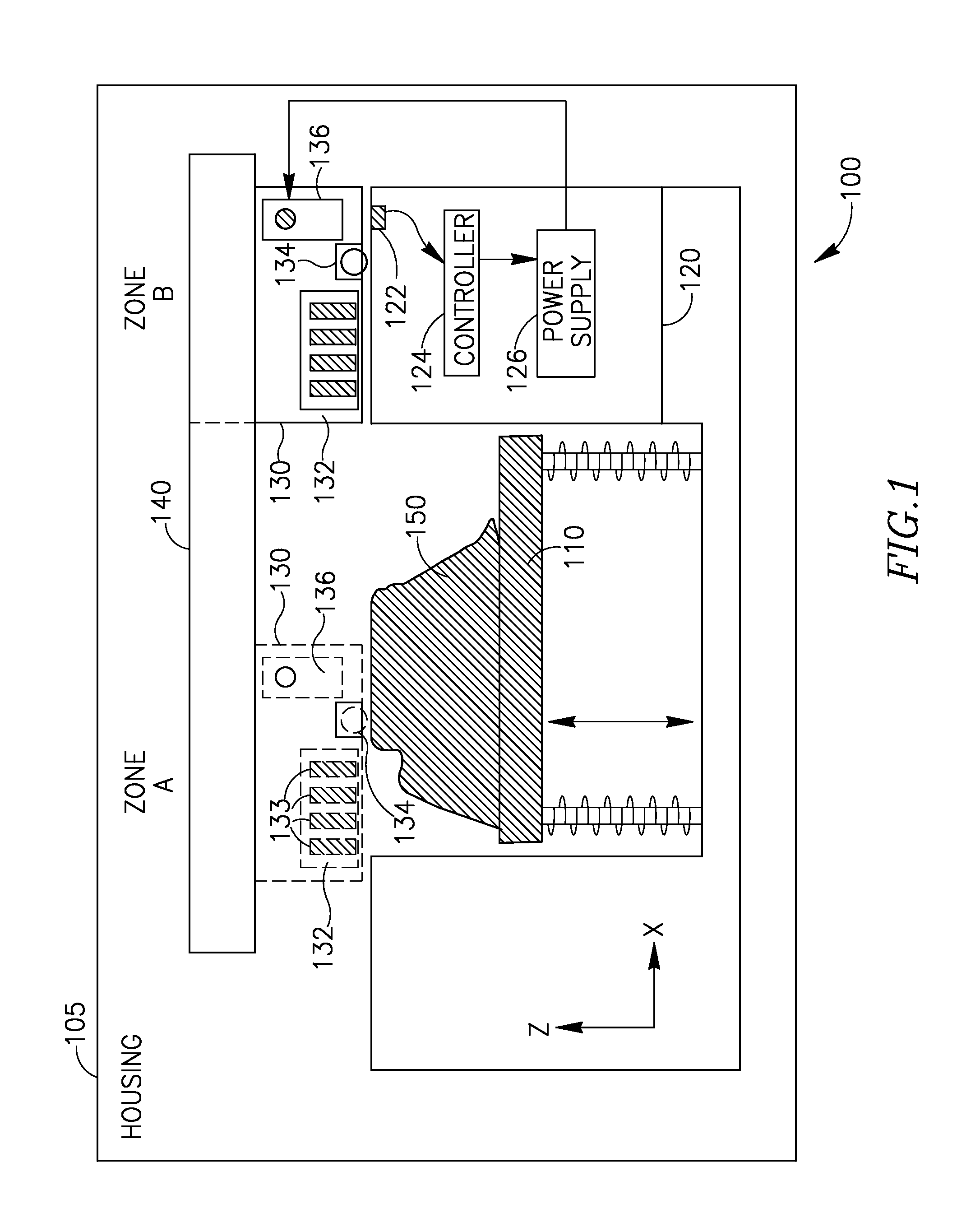
Embodiments of the present invention are directed to a system and method for controlling fabrication of three-dimensional objects, layer by layer, the system comprising a printing assembly, including an irradiation unit and a printing head, the printing assembly is movable between a printing area and a service area. A light sensor positioned at the service area to measure output radiation power of the irradiation unit at a printing plane and a controller to receive information from the sensor and to automatically adjust electrical power supplied to the irradiation unit based on the information.

Description

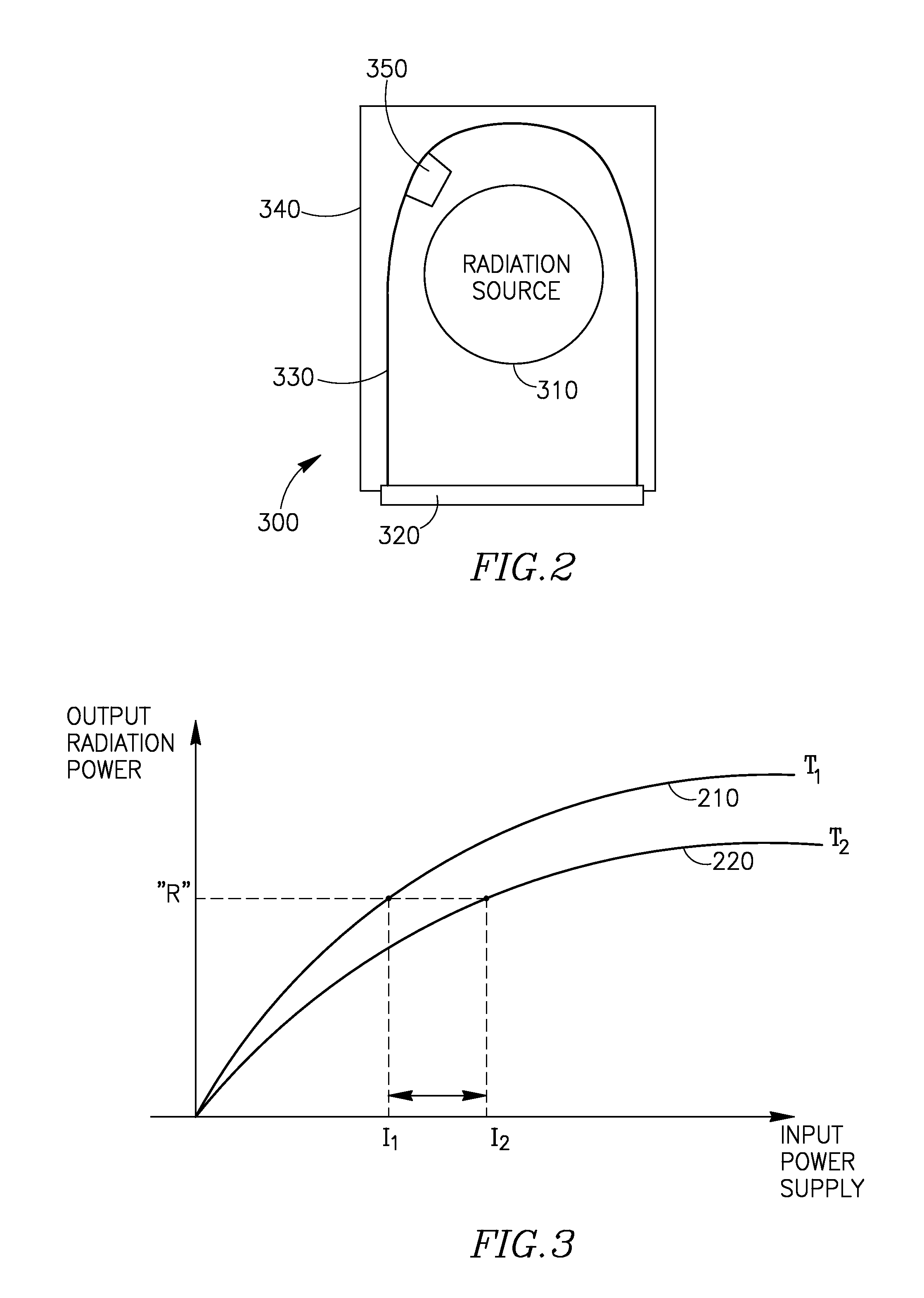
BACKGROUND OF THE INVENTION[0001]In three-dimensional printing, building material is selectively jetted from one or more printing heads and deposited onto a fabrication tray in consecutive layers according to a pre-determined image data. In printing machines that utilize photopolymers as building material, the liquid layers are solidified, conditioned or cured using a radiation source. The radiation source may emit light such as ultraviolet (UV) light according to predetermined working parameters, such as output radiation intensity and spectral region. Formation of high-quality 3D objects requires maintaining the radiation power and wavelength region substantially constant. For example, the radiation power may only vary within ±5%-±10%. The intensity of the light source, however, may decrease in more that 10% from various reasons including deterioration of the light source, deterioration of a reflector of the light source, appearance of mist or undesired splashes of material on the ...

Claims


Application Information

Patent Timeline
Patent Type & Authority Patents(United States)
IPC IPC(8): B29C67/00
CPCB29C67/0059B29C67/0088B29C64/112B33Y30/00B29C64/393B29C64/106B33Y50/02
Inventor KRITCHMAN, ELIAHU M.LIBINSON, ALEXANDERLEVI, MOSHEMENCHIK, GUY
Owner STRATASYS LTD
Learn More